


Create successful ePaper yourself
Turn your PDF publications into a flip-book with our unique Google optimized e-Paper software.
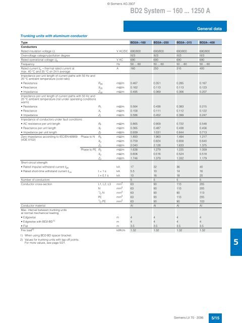
© Siemens AG 2007<br />
BD2 <strong>System</strong> — <strong>160</strong> ... 1250 A<br />
General data<br />
Trunking units with aluminum conductor<br />
Type BD2A-.-<strong>160</strong> BD2A-.-250 BD2A-.-315 BD2A-.-<strong>40</strong>0<br />
Conductors<br />
Rated insulation voltage U i V AC/DC 690/800 690/800 690/800 690/800<br />
Overvoltage category/pollution degree III/3 III/3 III/3 III/3<br />
Rated operational voltage U e V AC 690 690 690 690<br />
Frequency Hz 50 ... 60 50 ... 60 50 ... 60 50 ... 60<br />
Rated current I e = thermal rated current at<br />
A <strong>160</strong> 250 315 <strong>40</strong>0<br />
max. <strong>40</strong> °C and 35 °C on 24 h average<br />
Impedance per unit length of current paths with 50 Hz and<br />
20 °C ambient temperature (cold rails)<br />
•Resistance R 20 mΩ/m 0.467 0.351 0.285 0.167<br />
• Reactance X 20 mΩ/m 0.162 0.113 0.113 0.123<br />
• Impedance Z 20 mΩ/m 0.495 0.369 0.306 0.207<br />
Impedance per unit length of current paths with 50 Hz and<br />
20 °C ambient temperature (rail under operating conditions<br />
warm)<br />
•Resistance R 1 mΩ/m 0.564 0.438 0.383 0.215<br />
• Reactance X 1 mΩ/m 0.158 0.111 0.112 0.122<br />
• Impedance Z 1 mΩ/m 0.586 0.452 0.399 0.247<br />
Impedance of conductors under fault conditions<br />
• AC resistance per unit length R F mΩ/m 0.865 0.909 0.722 0.548<br />
• Reactance per unit length X F mΩ/m 0.365 0.487 0.438 0.456<br />
• Impedance per unit length Z F mΩ/m 0.939 1.031 0.844 0.713<br />
Zero impedance according to IEC/EN 60909 Phase to N R 0 mΩ/m 1.893 1.963 1.494 1.217<br />
(VDE 0102)<br />
X 0 mΩ/m 0.759 0.824 0.658 0.6<strong>40</strong><br />
Z 0 mΩ/m 2.0<strong>40</strong> 2.128 1.633 1.375<br />
Phase to PE R 0 mΩ/m 1.638 1.279 1.225 1.059<br />
X 0 mΩ/m 0.606 0.516 0.524 0.518<br />
Z 0 mΩ/m 1.746 1.379 1.332 1.179<br />
Short-circuit strength<br />
• Rated impulse withstand current I pk kA 17 32 36 <strong>40</strong><br />
• Rated short-time withstand current I cw t = 1 s kA 5.5 10 14 16<br />
t = 0.1 s kA 10 16 18 20<br />
Number of conductors 5 5 5 5<br />
Conductor cross-section L1, L2, L3 mm 2 63 90 113 205<br />
N mm 2 63 90 113 205<br />
1 / 2 N mm 2 63 90 90 113<br />
PE mm 2 63 90 113 205<br />
1 / 2 PE mm 2 63 90 90 103<br />
Conductor material Al Al Al Al<br />
Max. interval between trunking units<br />
at normal mechanical loading<br />
•Edgewise m 4 4 4 4<br />
• Edgewise with BD2-BD 1) m 4 4 4 4<br />
•Flat m 3.5 3.5 3.5 3.5<br />
Fire load 2) kWh/m 1.32 1.32 1.32 1.32<br />
1) When using BD2-BD spacer bracket.<br />
2) Values for trunking units with tap-off points.<br />
For more values, see page 5/21.<br />
5<br />
Siemens LV 70 · 2006<br />
5/15


