


You also want an ePaper? Increase the reach of your titles
YUMPU automatically turns print PDFs into web optimized ePapers that Google loves.
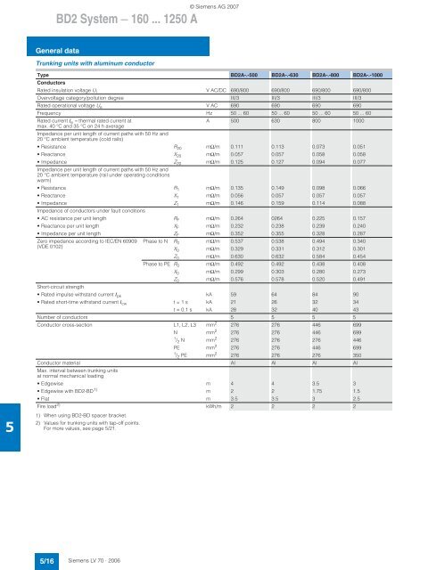
BD2 <strong>System</strong> — <strong>160</strong> ... 1250 A<br />
© Siemens AG 2007<br />
General data<br />
Trunking units with aluminum conductor<br />
Type BD2A-.-500 BD2A-.-630 BD2A-.-800 BD2A-.-1000<br />
Conductors<br />
Rated insulation voltage U i V AC/DC 690/800 690/800 690/800 690/800<br />
Overvoltage category/pollution degree III/3 III/3 III/3 III/3<br />
Rated operational voltage U e V AC 690 690 690 690<br />
Frequency Hz 50 ... 60 50 ... 60 50 ... 60 50 ... 60<br />
Rated current I e = thermal rated current at<br />
A 500 630 800 1000<br />
max. <strong>40</strong> °C and 35 °C on 24 h average<br />
Impedance per unit length of current paths with 50 Hz and<br />
20 °C ambient temperature (cold rails)<br />
•Resistance R 20 mΩ/m 0.111 0.113 0.073 0.051<br />
• Reactance X 20 mΩ/m 0.057 0.057 0.058 0.058<br />
• Impedance Z 20 mΩ/m 0.125 0.127 0.094 0.077<br />
Impedance per unit length of current paths with 50 Hz and<br />
20 °C ambient temperature (rail under operating conditions<br />
warm)<br />
•Resistance R 1 mΩ/m 0.135 0.149 0.098 0.066<br />
• Reactance X 1 mΩ/m 0.056 0.057 0.057 0.057<br />
• Impedance Z 1 mΩ/m 0.146 0.159 0.114 0.088<br />
Impedance of conductors under fault conditions<br />
• AC resistance per unit length R F mΩ/m 0.264 0264 0.225 0.157<br />
• Reactance per unit length X F mΩ/m 0.232 0.238 0.239 0.2<strong>40</strong><br />
• Impedance per unit length Z F mΩ/m 0.352 0.355 0.328 0.287<br />
Zero impedance according to IEC/EN 60909 Phase to N R 0 mΩ/m 0.537 0.538 0.494 0.3<strong>40</strong><br />
(VDE 0102)<br />
X 0 mΩ/m 0.329 0.331 0.312 0.301<br />
Z 0 mΩ/m 0.630 0.632 0.584 0.454<br />
Phase to PE R 0 mΩ/m 0.492 0.492 0.438 0.<strong>40</strong>8<br />
X 0 mΩ/m 0.299 0.303 0.280 0.273<br />
Z 0 mΩ/m 0.576 0.578 0.520 0.491<br />
Short-circuit strength<br />
• Rated impulse withstand current I pk kA 59 64 84 90<br />
• Rated short-time withstand current I cw t = 1 s kA 21 26 32 34<br />
t = 0.1 s kA 28 32 <strong>40</strong> 43<br />
Number of conductors 5 5 5 5<br />
Conductor cross-section L1, L2, L3 mm 2 276 276 446 699<br />
N mm 2 276 276 446 699<br />
1 / 2 N mm 2 276 276 276 446<br />
PE mm 2 276 276 446 699<br />
1 / 2 PE mm 2 276 276 276 350<br />
5<br />
Conductor material Al Al Al Al<br />
Max. interval between trunking units<br />
at normal mechanical loading<br />
•Edgewise m 4 4 3.5 3<br />
• Edgewise with BD2-BD 1) m 2 2 1.75 1.5<br />
•Flat m 3.5 3.5 3 2.5<br />
Fire load 2) kWh/m 2 2 2 2<br />
1) When using BD2-BD spacer bracket.<br />
2) Values for trunking units with tap-off points.<br />
For more values, see page 5/21.<br />
5/16 Siemens LV 70 · 2006


