- Page 3:
How to use this manual This manual
- Page 6 and 7:
SERVICE INFORMATION 1,910mm 750mm 1
- Page 8 and 9:
SERVICE INFORMATION 1-4
- Page 10 and 11:
SERVICE INFORMATION 1-6
- Page 12 and 13:
SERVICE INFORMATION 1-8
- Page 14 and 15:
SERVICE INFORMATION GENERAL SAFETY
- Page 16 and 17:
SERVICE INFORMATION 13. Check the s
- Page 18 and 19:
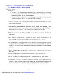
SERVICE INFORMATION CAUTION WHEN WI
- Page 20 and 21:
SERVICE INFORMATION •Insert the c
- Page 22 and 23:
MEMO
- Page 24 and 25: INSPECTIONS/ADJUSTMENTS 2-2
- Page 26 and 27: INSPECTIONS/ADJUSTMENTS FUEL PUMP F
- Page 28 and 29: INSPECTIONS/ADJUSTMENTS TIMINCT HOl
- Page 30 and 31: INSPECTIONS/ADJUSTMENTS MASTER CYLI
- Page 32 and 33: INSPECTIONS/ADJUSTMENTS TIRE PRESSU
- Page 34 and 35: MEMO
- Page 36 and 37: EXTERNAL PARTS MAINTENANCE PROCEDUR
- Page 38 and 39: EXTERNAL PARTS SPEEDOMETER ●Remov
- Page 40 and 41: EXTERNAL PARTS SPECIAL SCREW REAR U
- Page 42 and 43: EXTERNAL PARTS ●Remove the inner
- Page 44 and 45: MEMO
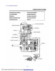
- Page 46 and 47: LUBRICATION SYSTEM Inclusion of wat
- Page 48 and 49: LUBRICATION SYSTEM FLANGE BOLTS OIL
- Page 50 and 51: LUBRICATION SYSTEM INNER ROTOR OUTE
- Page 52 and 53: LUBRICATION SYSTEM RADIATOR OIL CHE
- Page 54 and 55: EMS(Engine Management System) 1. CA
- Page 56 and 57: EMS(Engine Management System) 3. TE
- Page 58 and 59: EMS(Engine Management System) FAIL-
- Page 60 and 61: EMS(Engine Management System) HOW T
- Page 62 and 63: EMS(Engine Management System) HOW T
- Page 64 and 65: EMS(Engine Management System) CENTE
- Page 66 and 67: EMS(Engine Management System) DISAS
- Page 68 and 69: EMS(Engine Management System) INJEC
- Page 70 and 71: EMS(Engine Management System) MAPAT
- Page 72 and 73: EMS(Engine Management System) Check
- Page 76 and 77: EMS(Engine Management System) Check
- Page 78 and 79: EMS(Engine Management System) 1)CHE
- Page 80 and 81: EMS(Engine Management System) ISA I
- Page 82 and 83: EMS(Engine Management System) CHECK
- Page 84 and 85: EMS(Engine Management System) 1) CH
- Page 86 and 87: EMS(Engine Management System) 14.CH
- Page 88 and 89: EMS(Engine Management System) ● C
- Page 90 and 91: EMS(Engine Management System) 4) Ch
- Page 92 and 93: EMS(Engine Management System) FUEL
- Page 94 and 95: EMS(Engine Management System) 17.HO
- Page 96 and 97: EMS(Engine Management System) 18.HO
- Page 98 and 99: EMS(Engine Management System) 20.HO
- Page 100 and 101: MEMO
- Page 102 and 103: FUEL SYSTEM TROUBLESHOOTING The veh
- Page 104 and 105: FUEL SYSTEM THROTTLE CABLE LOCK NUT
- Page 106 and 107: FUEL SYSTEM ● Remove the main jet
- Page 108 and 109: FUEL SYSTEM COMPRESS STRAIGHT ! NOT
- Page 110 and 111: FUEL SYSTEM When idling, check to
- Page 112 and 113: FUEL SYSTEM ● Check the gaskets.
- Page 114 and 115: ENGINE REMOVAL/INSTALLATION DRAIN P
- Page 116 and 117: LH. CRANKCASE COVER/CONTINUOUSLY VA
- Page 118 and 119: LH.CRANK CASE COVER/CONTINUOUSLY VA
- Page 120 and 121: LH.CRANK CASE COVER/CONTINUOUSLY VA
- Page 122 and 123: LH.CRANK CASE COVER/CONTINUOUSLY VA
- Page 124 and 125:
LH.CRANK CASE COVER/CONTINUOUSLY VA
- Page 126 and 127:
LH.CRANK CASE COVER/CONTINUOUSLY VA
- Page 128 and 129:
LH.CRANK CASE COVER/CONTINUOUSLY VA
- Page 130 and 131:
A.C GENERATOR / STARTER CLUTCH STAR
- Page 132 and 133:
A.C GENERATOR / STARTER CLUTCH SAI
- Page 134 and 135:
A.C GENERATOR / STARTER CLUTCH STAR
- Page 136 and 137:
A.C GENERATOR / STARTER CLUTCH REDU
- Page 138 and 139:
A.C GENERATOR / STARTER CLUTCH STAR
- Page 140 and 141:
CYLINDER HEAD / VALVES FLANGE NUT I
- Page 142 and 143:
CYLINDER HEAD / VALVES TOOLS VALVE
- Page 144 and 145:
CYLINDER HEAD / VALVES ● Remove t
- Page 146 and 147:
CYLINDER HEAD / VALVES ● Remove t
- Page 148 and 149:
CYLINDER HEAD / VALVES VALVE GUIDE
- Page 150 and 151:
CYLINDER HEAD / VALVES ● Using a
- Page 152 and 153:
CYLINDER HEAD / VALVES ● Tap the
- Page 154 and 155:
CYLINDER HEAD / VALVES CAM SHAFT
- Page 156 and 157:
CYLINDER / PISTON CYLINDER TOP RING
- Page 158 and 159:
CYLINDER / PISTON CYLINDER CYLINDER
- Page 160 and 161:
CYLINDER / PISTON 11-4
- Page 162 and 163:
CYLINDER / PISTON CYLINDER GASKET P
- Page 164 and 165:
TRANSMISSION/CRANKSHAFT/CRANK CASE
- Page 166 and 167:
TRANSMISSION/CRANKSHAFT/CRANK CASE
- Page 168 and 169:
TRANSMISSION/CRANKSHAFT/CRANK CASE
- Page 170 and 171:
TRANSMISSION/CRANKSHAFT/CRANK CASE
- Page 172 and 173:
TRANSMISSION/CRANKSHAFT/CRANK CASE
- Page 174 and 175:
TRANSMISSION/CRANKSHAFT/CRANK CASE
- Page 176 and 177:
FRONT WHEEL/FRONT FORK/STEERING STE
- Page 178 and 179:
FRONT WHEEL/FRONT FORK/STEERING TRO
- Page 180 and 181:
FRONT WHEEL/FRONT FORK/STEERING STE
- Page 182 and 183:
FRONT WHEEL/FRONT FORK/STEERING SPE
- Page 184 and 185:
FRONT WHEEL/FRONT FORK/STEERING ●
- Page 186 and 187:
FRONT WHEEL/FRONT FORK/STEERING FRO
- Page 188 and 189:
FRONT WHEEL/FRONT FORK/STEERING FOR
- Page 190 and 191:
REAR WHEEL/SUSPENSION/REAR SWING AR
- Page 192 and 193:
REAR WHEEL/SUSPENSION/REAR SWING AR
- Page 194 and 195:
REAR WHEEL/SUSPENSION/REAR SWING AR
- Page 196 and 197:
REAR WHEEL/SUSPENSION/REAR SWING AR
- Page 198 and 199:
MEMO
- Page 200 and 201:
BRAKE SYSTEM 15-0
- Page 202 and 203:
BRAKE SYSTEM TROUBLESHOOTING Brake
- Page 204 and 205:
BRAKE SYSTEM BREEDER VALVE BREEDER
- Page 206 and 207:
BRAKE SYSTEM RR. CALIPER LOCK PLATE
- Page 208 and 209:
BRAKE SYSTEM LH CALIPER BODY HANGER
- Page 210 and 211:
BRAKE SYSTEM CALIPER COMP RH.SIM(DC
- Page 212 and 213:
BRAKE SYSTEM PISTON INSPECTION ●
- Page 214 and 215:
CHARGING SYSTEM 15A 16-0
- Page 216 and 217:
CHARGING SYSTEM TROUBLESHOOTING No
- Page 218 and 219:
CHARGING SYSTEM AMPERE METER BATTER
- Page 220 and 221:
IGNITION SYSTEM IGNITION SYSYTEM SI
- Page 222 and 223:
IGNITION SYSTEM TROUBLESHOOTING No
- Page 224 and 225:
IGNITION SYSTEM IGNITION COIL INSPE
- Page 226 and 227:
STARTER SYSTEM STARTER SYSTEM CABLE
- Page 228 and 229:
STARTER SYSTEM TROUBLESHOOTING Star
- Page 230 and 231:
STARTER SYSTEM BRUSH ● Remove the
- Page 232 and 233:
STARTER SYSTEM STARTER MAGNETIC SWI
- Page 234 and 235:
MEMO
- Page 236 and 237:
LIGHTS/SWITCHES/HORN HEAD LIGHT HEA
- Page 238 and 239:
LIGHTS/SWITCHES/HORN MAIN SWITCH MA
- Page 240 and 241:
LIGHTS/SWITCHES/HORN FUEL TANK FUEL
- Page 242 and 243:
MEMO
- Page 244 and 245:
20-2. WIRING DIAGRAM (EURO-3) WIRIN
- Page 246:
SM57-0902-01E