- Page 1 and 2:
MIC 1462 1/4 DIN SETPOINT PROGRAMME
- Page 3 and 4:
Table of Contents Section 1 - Gener
- Page 5 and 6:
Figures Figure 1-1 Front Panel 2 Fi
- Page 7 and 8:
Section 1 - General 1.1 PRODUCT DES
- Page 9 and 10:
Section 2 - Installation & Wiring 2
- Page 11 and 12:
Once the instrument is installed in
- Page 13 and 14:
The only wires that should run toge
- Page 15 and 16:
2.3.5 SENSOR PLACEMENT (THERMOCOUPL
- Page 17 and 18:
FIGURE 2-6A REMOTE INPUTS R0 R1 R2
- Page 19 and 20:
FIGURE 2-7A 24V Nominal AC/DC Suppl
- Page 21 and 22:
FIGURE 2-12 Remote Digital Communic
- Page 23 and 24:
FIGURE 2-18 mADC Output 2 (Control
- Page 25 and 26:
FIGURE 2-24 End of Program Output C
- Page 27 and 28:
precedence over the corresponding f
- Page 29 and 30:
Section 3 - Operation 3.1 POWER UP
- Page 31 and 32:
3.3 INDICATORS Control Status Indic
- Page 33 and 34:
3.6 VIEWING PROGRAM AND CONTROLLER
- Page 35 and 36:
3.9 BASE MODE AND OFF MODE OUTPUTS
- Page 37 and 38:
To de-activate the Pre-Tune facilit
- Page 39 and 40:
4.2 HARDWARE DEFINITION CODE This p
- Page 41 and 42:
Press the SCROLL key to change the
- Page 43 and 44:
MESSAGE AVAILABLE STEP DESCRIPTION
- Page 45 and 46:
MESSAGE AVAILABLE STEP DESCRIPTION
- Page 47 and 48:
Notes on Configuration Mode Paramet
- Page 49 and 50:
5.1 TUNE PARAMETERS The Controller
- Page 51 and 52:
11 Manual Reset (3) Man Rset Bias a
- Page 53 and 54:
FIGURE 5-1 Output Power (%) Output
- Page 55 and 56:
Section 6 - Alarm Mode The Alarm Mo
- Page 57 and 58: 4d Deviation DeAlarm 1 If Alarm 1 i
- Page 59 and 60: MESSAGE AVAILABLE STEP DESCRIPTION
- Page 61 and 62: FIGURE 6-1 Edition 1 55 MIC 1462 Ma
- Page 63 and 64: FIGURE 6.2 Edition 1 57 MIC 1462 Ma
- Page 65 and 66: 7.2 PARAMETERS COMMON TO ALL PROFIL
- Page 67 and 68: does not appear program runif recov
- Page 69 and 70: MESSAGE AVAILABLE STEP DESCRIPTION
- Page 71 and 72: This parameter sequence may be view
- Page 73 and 74: MESSAGE AVAILABLE STEP DESCRIPTION
- Page 75 and 76: 7.5 USING JOIN, REPEAT AND END SEGM
- Page 77 and 78: Now, with Program 2 set to perform
- Page 79 and 80: 8.4 JUMPING TO THE NEXT SEGMENT At
- Page 81 and 82: 8.8 ACCESSING MODES OF THE CONTROLL
- Page 83 and 84: Section 10 - Calibration Mode To en
- Page 85 and 86: TABLE 10.1 Universal Input Type Sel
- Page 87 and 88: Appendix A - Range Codes The input
- Page 89 and 90: Appendix B - Board Layout, Jumper P
- Page 91 and 92: FIGURE B-3 CPU PWA LJ3 LJ2 LJ1 IC6
- Page 93 and 94: FIGURE B-5 PWA WITH DC OUTPUT 1 TX1
- Page 95 and 96: Appendix C - Specifications INPUT S
- Page 97 and 98: Isolation: SSR Driver/TTL Drive Cap
- Page 99 and 100: Alarms Maximum Number: Maximum # Ou
- Page 101 and 102: Performance Under Reference Conditi
- Page 103 and 104: PHYSICAL Dimensions: Mounting: 1/4
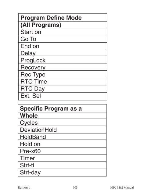
- Page 105 and 106: Appendix E - Software Reference She
- Page 107: Tune Mode Inp Cor Po1 Po2 P. Out HI
- Page 111 and 112: Warranty and Return Statement These