MIC1462 manual.pdf
MIC1462 manual.pdf
MIC1462 manual.pdf

Create successful ePaper yourself
Turn your PDF publications into a flip-book with our unique Google optimized e-Paper software.
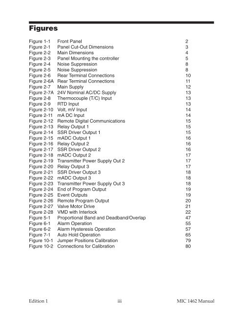
Figures<br />
Figure 1-1 Front Panel 2<br />
Figure 2-1 Panel Cut-Out Dimensions 3<br />
Figure 2-2 Main Dimensions 4<br />
Figure 2-3 Panel Mounting the controller 5<br />
Figure 2-4 Noise Suppression 8<br />
Figure 2-5 Noise Suppression 8<br />
Figure 2-6 Rear Terminal Connections 10<br />
Figure 2-6A Rear Terminal Connections 11<br />
Figure 2-7 Main Supply 12<br />
Figure 2-7A 24V Nominal AC/DC Supply 13<br />
Figure 2-8 Thermocouple (T/C) Input 13<br />
Figure 2-9 RTD Input 13<br />
Figure 2-10 Volt, mV Input 14<br />
Figure 2-11 mA DC Input 14<br />
Figure 2-12 Remote Digital Communications 15<br />
Figure 2-13 Relay Output 1 15<br />
Figure 2-14 SSR Driver Output 1 15<br />
Figure 2-15 mADC Output 1 16<br />
Figure 2-16 Relay Output 2 16<br />
Figure 2-17 SSR Driver Output 2 16<br />
Figure 2-18 mADC Output 2 17<br />
Figure 2-19 Transmitter Power Supply Out 2 17<br />
Figure 2-20 Relay Output 3 17<br />
Figure 2-21 SSR Driver Output 3 18<br />
Figure 2-22 mADC Output 3 18<br />
Figure 2-23 Transmitter Power Supply Out 3 18<br />
Figure 2-24 End of Program Output 19<br />
Figure 2-25 Event Outputs 19<br />
Figure 2-26 Remote Program Output 20<br />
Figure 2-27 Valve Motor Drive 21<br />
Figure 2-28 VMD with Interlock 22<br />
Figure 5-1 Proportional Band and Deadband/Overlap 47<br />
Figure 6-1 Alarm Operation 55<br />
Figure 6-2 Alarm Hysteresis Operation 57<br />
Figure 7-1 Auto Hold Operation 65<br />
Figure 10-1 Jumper Positions Calibration 79<br />
Figure 10-2 Connections for Calibration 80<br />
Edition 1<br />
iii<br />
MIC 1462 Manual