MIC1462 manual.pdf
MIC1462 manual.pdf
MIC1462 manual.pdf

Create successful ePaper yourself
Turn your PDF publications into a flip-book with our unique Google optimized e-Paper software.
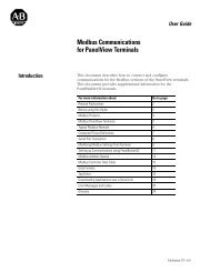
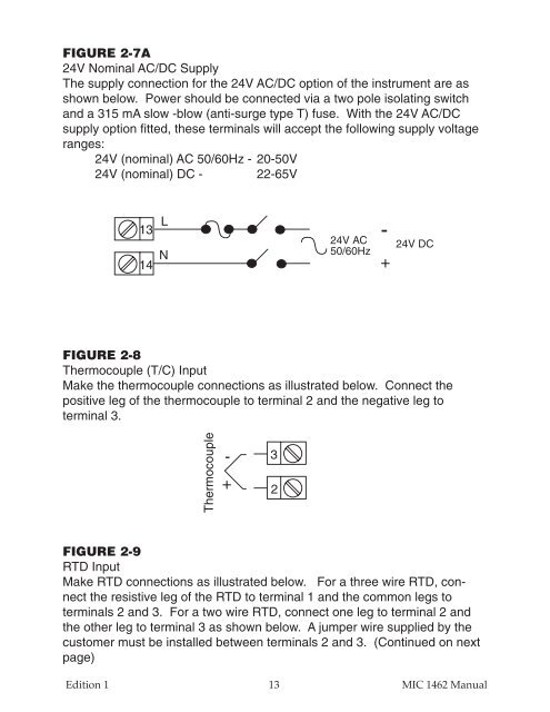
FIGURE 2-7A<br />
24V Nominal AC/DC Supply<br />
The supply connection for the 24V AC/DC option of the instrument are as<br />
shown below. Power should be connected via a two pole isolating switch<br />
and a 315 mA slow -blow (anti-surge type T) fuse. With the 24V AC/DC<br />
supply option fitted, these terminals will accept the following supply voltage<br />
ranges:<br />
24V (nominal) AC 50/60Hz - 20-50V<br />
24V (nominal) DC - 22-65V<br />
13<br />
14<br />
L<br />
N<br />
24V AC<br />
50/60Hz<br />
-<br />
+<br />
24V DC<br />
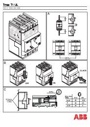
FIGURE 2-8<br />
Thermocouple (T/C) Input<br />
Make the thermocouple connections as illustrated below. Connect the<br />
positive leg of the thermocouple to terminal 2 and the negative leg to<br />
terminal 3.<br />
Thermocouple<br />
-<br />
+<br />
3<br />
2<br />
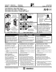
FIGURE 2-9<br />
RTD Input<br />
Make RTD connections as illustrated below. For a three wire RTD, connect<br />
the resistive leg of the RTD to terminal 1 and the common legs to<br />
terminals 2 and 3. For a two wire RTD, connect one leg to terminal 2 and<br />
the other leg to terminal 3 as shown below. A jumper wire supplied by the<br />
customer must be installed between terminals 2 and 3. (Continued on next<br />
page)<br />
Edition 1<br />
13 MIC 1462 Manual