MIC1462 manual.pdf
MIC1462 manual.pdf
MIC1462 manual.pdf

You also want an ePaper? Increase the reach of your titles
YUMPU automatically turns print PDFs into web optimized ePapers that Google loves.
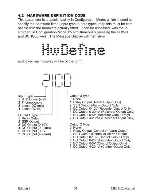
4.2 HARDWARE DEFINITION CODE<br />
This parameter is a special facility in Configuration Mode, which is used to<br />
specify the hardware fitted (input type, output types, etc); this must be compatible<br />
with the hardware actually fitted. It can be accessed, with the instrument<br />
in Configuration Mode, by simultaneously pressing the DOWN<br />
and SCROLL keys. The Message Display will then show:<br />
and lower main display will be of the form:<br />
Input Type<br />
1 RTD/Linear (mV)<br />
2 Thermocouple<br />
3 Linear DC (mA)<br />
4 Linear DC (V)<br />
Output 1 Type<br />
1 Relay Output<br />
2 SSR Output<br />
3 DC Output (0-10V)<br />
4 DC Output (0-20mA)<br />
5 DC Output (0-5V)<br />
7 DC Output (4-20mA)<br />
Output 3 Type<br />
0 None<br />
1 Relay Output (Alarm Output Only)<br />
2 SSR Output (Alarm Output Only)<br />
3 DC Output 0-10V (Recorder Output Only)<br />
4 DC Output 0-20mA (Recorder Output Only)<br />
5 DC Output 0-5V (Recorder Output Only)<br />
7 DC Output 4-20mA (Recorder Output Only)<br />
Output 2 Type<br />
0 None<br />
1 Relay Output (Control or Alarm Output)<br />
2 SSR Output (Control or Alarm Output)<br />
3 DC Output 0-10V (Control Output Only)<br />
4 DC Output 0-20mA (Control Output Only)<br />
5 DC Output 0-5V (Control Output Only)<br />
7 DC Output 4-20mA (Control Output Only)<br />
Edition 1<br />
33 MIC 1462 Manual