Space Grant Consortium - University of Wisconsin - Green Bay
Space Grant Consortium - University of Wisconsin - Green Bay
Space Grant Consortium - University of Wisconsin - Green Bay

Create successful ePaper yourself
Turn your PDF publications into a flip-book with our unique Google optimized e-Paper software.
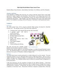
Our Design<br />
Our rocket uses the basic laws <strong>of</strong> physics in concept and design. The booster is simply meant to<br />
push the dart upwards. Knowing this we wanted to design it as aerodynamically and light as possible.<br />
We decided to use a boattail on the booster because this makes the booster, and the rocket in its<br />
entirety, more aerodynamic. It does this by minimizing the disturbance as the air comes back together<br />
at the end <strong>of</strong> the rocket. In keeping with the light design we went with a plastic boattail instead <strong>of</strong> a<br />
fiberglass one. We believe that it will be strong enough. At the end <strong>of</strong> the boattail we have a threaded<br />
cap for motor retention. It allows for easy retention without having to deal with threaded rod through<br />
the boattail going to nuts holding a washer.<br />
The body is the required 4” body tube. We choose a phenolic airframe. This again is because we want a<br />
very light design and believe that a phenolic tube will still be strong enough. We cut the tube very<br />
short, roughly a foot; to make the booster light. More importantly however is the aerodynamics <strong>of</strong> the<br />
design. We want the booster to create as little drag as possible thus making it short. Simply put, drag is<br />
directly proportional to surface area; the more surface area the more drag. Within the body <strong>of</strong> booster<br />
we used as few centering rings and bulk plates as possible. This reduces weight. We will be using<br />
motor eject for the booster. This is because it is the simplest and is all we need for the booster.<br />
The nosecone for the booster is different from most rockets. Because the rocket has a dart<br />
coming out <strong>of</strong> it we decided to turn a plastic nosecone into a custom boattail. What this allows us to do<br />
is to recede the dart into the nosecone making the overlap length longer. Having a longer overlapping<br />
length makes the rocket less flimsy where the dart comes out. Having the rocket less flimsy reduces the<br />
amount <strong>of</strong> energy lost when the rocket ascends.<br />
The dart consists <strong>of</strong> a plastic nosecone on each end. This is for the same reason as the boattail<br />
on the booster. It makes the dart more aerodynamic. The airframe is made <strong>of</strong> phenolic tube same as the<br />
booster; this is due to the weight advantage. We made the dart three feet long. Inside the airframe we<br />
have two electronics bays. The judges’ is in the back end <strong>of</strong> the dart, just in front <strong>of</strong> the fins. In the<br />
front <strong>of</strong> the dart are our electronics. We are using Missile Works’ RRC2-mini Rocket Recovery<br />
Controller 1.2 This will record altitude, but more importantly it will ignite the charges the blow the<br />
chute after apogee. Between the two electronics bays is a parachute connected by a shock cord. In the<br />
front is a plastic nosecone.<br />
The back nosecone was converted into a slight boattail. We cut <strong>of</strong>f the tip <strong>of</strong> the back nosecone,<br />
turning it into the slight boattail. We cut it so that the hole was just large enough for the brass tube to<br />
fit. The other end was secured by a bulk plate with a hole cut into the center. In the front boattail <strong>of</strong> the<br />
booster is a long nail, roughly ten inches long. This nail is held in the front bulk plate with epoxy. The<br />
brass tube slips over the nail. The rod will be used to guide the dart <strong>of</strong>f the booster. This allows for a<br />
relatively frictionless separation between the booster and the dart. This is key in our design.<br />
The difficult part <strong>of</strong> designing the rocket was to ensure balance the center <strong>of</strong> pressure and center <strong>of</strong><br />
gravity at specific ratios. It was calculated that for the utmost performance the center <strong>of</strong> pressure<br />
should be located 1.5 to 2 times the diameter behind the center <strong>of</strong> gravity. This will allow for the most<br />
efficient thrust and achieve the highest altitude/performance possible. The center <strong>of</strong> pressure is<br />
determined by the geometry <strong>of</strong> the rocket and was checked using the simulation program RockSim 8.<br />
The center <strong>of</strong> gravity; however, was found by locating the point on the rocket where it balanced on a<br />
fulcrum.<br />
26