
Create successful ePaper yourself
Turn your PDF publications into a flip-book with our unique Google optimized e-Paper software.
LIST OF ATTACHMENTSBASIS FOR CALCULATIONS<br />
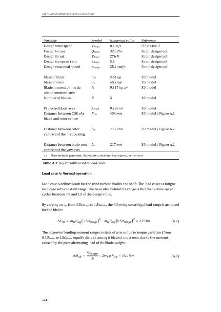
Variable Symbol Numerical value Reference<br />
Design wind speed Vdesign 8.4 m/s IEC 61400-2<br />
Design torque Qdesign 32.5 Nm Rotor design tool<br />
Design thrust Tdesign 276 N Rotor design tool<br />
Design tip-speed ratio �design 5.6 Rotor design tool<br />
Design rotational speed �design 35.1 rad/s Rotor design tool<br />
Mass of blade mB 2.61 kg 3D model<br />
Mass of rotor mr 45.2 kg a 3D model<br />
Blade moment of inertia<br />
about rotational axis<br />
124<br />
IB 0.317 kg m 2 3D model<br />
Number of blades B 3 3D model<br />
Projected blade area Aproj.B 0.230 m 2 3D model<br />
Distance between COG of a<br />
blade and rotor centre<br />
Distance between rotor<br />
centre and the first bearing<br />
Distance between blade root<br />
centre and the yaw axis<br />
Rcog 434 mm 3D model / Figure A.2<br />
Lrb 77.7 mm 3D model / Figure A.2<br />
Lrt 217 mm 3D model / Figure A.2<br />
a) Mass includes generator, blades, bolts, washers, bearings etc. in the rotor<br />
Table A.3: Key variables used in load cases<br />
Load case A: Normal operation<br />
Load case A defines loads for the wind turbine blades and shaft. The load case is a fatigue<br />
load case with constant range. The basic idea behind the range is that the turbine speed<br />
cycles between 0.5 and 1.5 of the design value.<br />
By varying �design from 0.5�design to 1.5�design the following centrifugal load range is achieved<br />
for the blades<br />
�F zB<br />
� �2 mB Rcog �0.5�design �2 � mB Rcog 1.5�design The edgewise bending moment range consists of a term due to torque variation (from<br />
0.5Qdesign to 1.5Qdesign equally divided among B blades) and a term due to the moment<br />
caused by the pure alternating load of the blade weight:<br />
� � 2.79 kN<br />
Qdesign �M xB �<br />
� 2mB g Rcog � 33.1 N m<br />
B<br />
(A.2)<br />
(A.3)