
You also want an ePaper? Increase the reach of your titles
YUMPU automatically turns print PDFs into web optimized ePapers that Google loves.
6.3 Rotor performance<br />
Aerodynamic rotor performance calculations are carried out u<strong>sin</strong>g an iterative rotor de-<br />
sign tool that has been developed as a part of this project on basis of the blade element<br />
momentum (BEM) theory, described in appendix B.1. The rotor design tool enables calcu-<br />
lation of aerodynamic flow conditions, forces, blade shape and rotor performance. It is<br />
intended to be used by EWB in the development of future wind turbines and it is thus de-<br />
signed with a spreadsheet interface that provides a certain degree of user-friendliness.<br />
ROTOR<br />
Details about the design tool, its functions, limitations and usage, can be found in appendix<br />
C.<br />
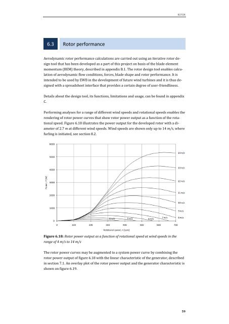
Performing analyses for a range of different wind speeds and rotational speeds enables the<br />
rendering of rotor power curves that show rotor power output as a function of the rota-<br />
tional speed. Figure 6.18 illustrates the power output for the developed rotor with a di-<br />
ameter of 2.7 m at different wind speeds. Wind speeds are shown only up to 14 m/s, where<br />
furling is initiated, see section 8.2.<br />
Figure 6.18: Rotor power output as a function of rotational speed at wind speeds in the<br />
range of 4 m/s to 14 m/s<br />
The rotor power curves may be augmented to a system power curve by combining the<br />
rotor power output of figure 6.18 with the linear characteristic of the generator, described<br />
in section 7.1. An overlay plot of the rotor power output and the generator characteristic is<br />
shown on figure 6.19.<br />
59