
You also want an ePaper? Increase the reach of your titles
YUMPU automatically turns print PDFs into web optimized ePapers that Google loves.
YAW AND FURLING<br />
(16), which are bolted onto the base plate u<strong>sin</strong>g two M16 bolts each. Rotation of the shaft<br />
is prevented by parallel key connection between the shaft and the rear block (16). Axial<br />
motion of the shaft is prevented with the retaining washer (17) that is connected to the<br />
shaft with a M30x1.5 thread and bolted into the rear generator block with 4 pcs. M10<br />
bolts (18). The tail boom of the wind turbine is mounted on an inclined pivot pin (20),<br />
which has a lower and upper diameter of ø45 mm and ø35 mm, respectively. The diamet-<br />
rical step is made with a 4 mm radius to reduce notch effect. A tail stop (21) is welded<br />
onto the pivot pin with the purpose of limiting the movement of the tail vane. The entire<br />
pivot system is welded onto the outer yaw pipe by means of two 5 mm fastening plates<br />
(22). The pivot system is tilted backwards 40� and it is angled 45� about the z-axis with<br />
reference to the xz-plane of figure 8.4. The inclinations are key parameters of the furling<br />
system, which is described in section 8.2 and appendix I.2.<br />
The remaining parts of the yaw system are shown below on figure 8.5, which is followed<br />
by a component description.<br />
78<br />
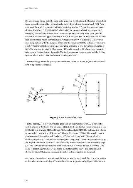
Figure 8.5: Tail boom and tail vane<br />
The tail boom (23) is a 1960 mm steel pipe with an outer diameter of 33.70 mm and a<br />
wall thickness of 4.00 mm. The tail vane (24) is bolted onto the tail boom by means of two<br />
8x30x800 mm brackets (26) and 8 pcs. M10 cup head bolts (25). The tail vane is a 10 mm<br />
wooden plate, measuring 1300 mm by 900 mm. The sleeve (27) is a 45 mm cold-drawn<br />
precision steel pipe with a wall thickness of 5 mm and a length of 220 mm, which is<br />
welded onto the tail boom with an 8 mm support plate (31). The tail boom and the sleeve<br />
are angled, so that the tail vane is vertical during normal operation. The bronze bearings<br />
(28) and (29) are mounted in both ends of the sleeve to reduce friction. A tail stop (30),<br />
equal to that of figure 8.4, is welded onto the bottom of the sleeve and a M6 bolt, not<br />
shown on figure 8.5, is used to secure the entire tail vane system on the pivot.<br />
Appendix I.1 contains a calculation of the yawing system, which validates the dimensions<br />
of the tail vane and the ability of the wind turbine to approximately align itself in a situa-