
You also want an ePaper? Increase the reach of your titles
YUMPU automatically turns print PDFs into web optimized ePapers that Google loves.
LIST OF ATTACHMENTSSTRUCTURAL ANALYSIS OF BLADES<br />
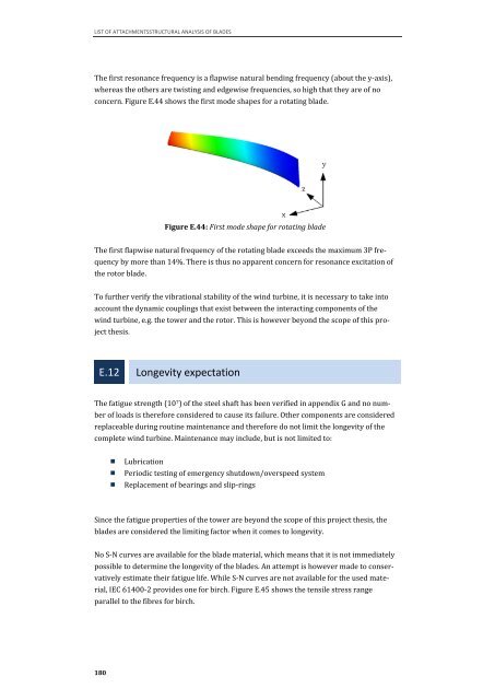
The first resonance frequency is a flapwise natural bending frequency (about the y-axis),<br />
whereas the others are twisting and edgewise frequencies, so high that they are of no<br />
concern. Figure E.44 shows the first mode shapes for a rotating blade.<br />
180<br />
Figure E.44: First mode shape for rotating blade<br />
The first flapwise natural frequency of the rotating blade exceeds the maximum 3P fre-<br />
quency by more than 14%. There is thus no apparent concern for resonance excitation of<br />
the rotor blade.<br />
To further verify the vibrational stability of the wind turbine, it is necessary to take into<br />
account the dynamic couplings that exist between the interacting components of the<br />
wind turbine, e.g. the tower and the rotor. This is however beyond the scope of this pro-<br />
ject thesis.<br />
E.12 Longevity expectation<br />
The fatigue strength (10 7 ) of the steel shaft has been verified in appendix G and no num-<br />
ber of loads is therefore considered to cause its failure. Other components are considered<br />
replaceable during routine maintenance and therefore do not limit the longevity of the<br />
complete wind turbine. Maintenance may include, but is not limited to:<br />
� Lubrication<br />
� Periodic testing of emergency shutdown/overspeed system<br />
� Replacement of bearings and slip-rings<br />
Since the fatigue properties of the tower are beyond the scope of this project thesis, the<br />
blades are considered the limiting factor when it comes to longevity.<br />
No S-N curves are available for the blade material, which means that it is not immediately<br />
possible to determine the longevity of the blades. An attempt is however made to conser-<br />
vatively estimate their fatigue life. While S-N curves are not available for the used mate-<br />
rial, IEC 61400-2 provides one for birch. Figure E.45 shows the tensile stress range<br />
parallel to the fibres for birch.