
You also want an ePaper? Increase the reach of your titles
YUMPU automatically turns print PDFs into web optimized ePapers that Google loves.
LIST OF ATTACHMENTSBASIS FOR CALCULATIONS<br />
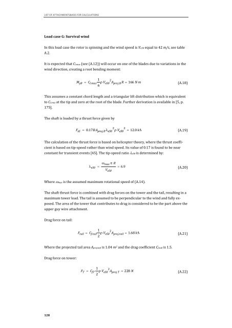
Load case G: Survival wind<br />
In this load case the rotor is spinning and the wind speed is Ve50 equal to 42 m/s, see table<br />
A.2.<br />
It is expected that Cl.max (see (A.12)) will occur on one of the blades due to variations in the<br />
wind direction, creating a root bending moment:<br />
128<br />
(A.18)<br />
This assumes a constant chord length and a triangular lift distribution which is equivalent<br />
to Cl.max at the tip and zero at the root of the blade. Further derivation is available in [5, p.<br />
175].<br />
The shaft is loaded by a thrust force given by<br />
The calculation of the thrust force is based on helicopter theory, where the thrust coeffi-<br />
cient is based on tip-speed rather than wind speed. Its value of 0.17 is found to be near<br />
constant for transient events [45]. The tip-speed ratio �e50 is determined by:<br />
Where �max is the assumed maximum rotational speed of (A.14).<br />
(A.19)<br />
(A.20)<br />
The shaft thrust force is combined with drag forces on the tower and the tail, resulting in a<br />
maximum tower load. The tail is assumed to be perpendicular to the wind and fully ex-<br />
posed. The area of the tower that contributes to drag is considered to be the part above the<br />
upper guy wire attachment.<br />
Drag force on tail:<br />
Where the projected tail area Aproj.tail is 1.04 m 2 and the drag coefficient Cf.tail is 1.5.<br />
Drag force on tower:<br />
M yB<br />
F xS<br />
�<br />
1<br />
Cl.max 6 � Ve50 2 Aproj.B R � 166 N m<br />
2 2<br />
� 0.17BAproj.B� e50 � Ve50 � 12.0 kN<br />
Ftail �<br />
� e50<br />
�<br />
� max � R<br />
V e50<br />
� 6.9<br />
1<br />
Cf.tail 2 � Ve50 2 Aproj.tail � 1.68 kN<br />
1<br />
FT CfT 2 � Ve50 2 �<br />
Aproj.T � 228 N<br />
(A.21)<br />
(A.22)