
Create successful ePaper yourself
Turn your PDF publications into a flip-book with our unique Google optimized e-Paper software.
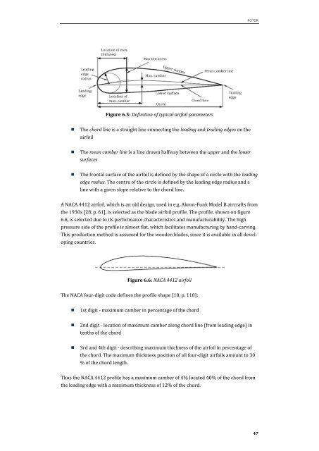
Figure 6.5: Definition of typical airfoil parameters<br />
� The chord line is a straight line connecting the leading and trailing edges on the<br />
airfoil<br />
� The mean camber line is a line drawn halfway between the upper and the lower<br />
surfaces<br />
ROTOR<br />
� The frontal surface of the airfoil is defined by the shape of a circle with the leading<br />
edge radius. The centre of the circle is defined by the leading edge radius and a<br />
line with a given slope relative to the chord line.<br />
A NACA 4412 airfoil, which is an old design, used in e.g. Akron-Funk Model B aircrafts from<br />
the 1930s [28, p. 61], is selected as the blade airfoil profile. The profile, shown on figure<br />
6.6, is selected due to its performance characteristics and manufacturability. The high<br />
pressure side of the profile is almost flat, which facilitates manufacturing by hand-carving.<br />
This production method is assumed for the wooden blades, <strong>sin</strong>ce it is available in all devel-<br />
oping countries.<br />
Figure 6.6: NACA 4412 airfoil<br />
The NACA four-digit code defines the profile shape [10, p. 110]:<br />
� 1st digit - maximum camber in percentage of the chord<br />
� 2nd digit - location of maximum camber along chord line (from leading edge) in<br />
tenths of the chord<br />
� 3rd and 4th digit - describing maximum thickness of the airfoil in percentage of<br />
the chord. The maximum thickness position of all four-digit airfoils amount to 30<br />
% of the chord length.<br />
Thus the NACA 4412 profile has a maximum camber of 4% located 40% of the chord from<br />
the leading edge with a maximum thickness of 12% of the chord.<br />
47