
Create successful ePaper yourself
Turn your PDF publications into a flip-book with our unique Google optimized e-Paper software.
CONCEPTUALISATION<br />
the kinetic wind energy, transform it into mechanical energy in a shaft and finally into<br />
electrical energy in a generator.<br />
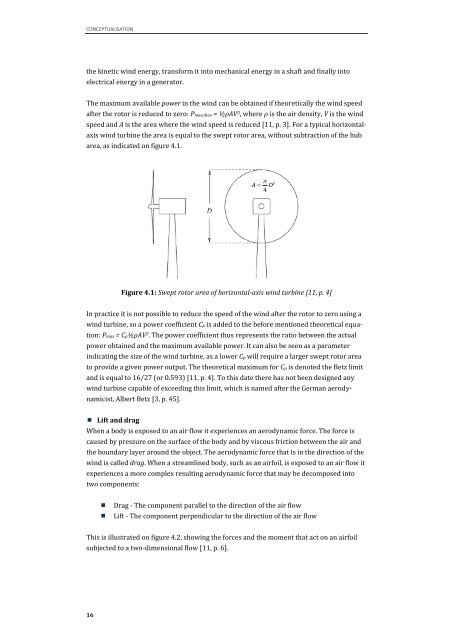
The maximum available power in the wind can be obtained if theoretically the wind speed<br />
after the rotor is reduced to zero: Pmax,theo = ½ρAV 3 , where ρ is the air density, V is the wind<br />
speed and A is the area where the wind speed is reduced [11, p. 3]. For a typical horizontal-<br />
axis wind turbine the area is equal to the swept rotor area, without subtraction of the hub<br />
area, as indicated on figure 4.1.<br />
16<br />
Figure 4.1: Swept rotor area of horizontal-axis wind turbine [11, p. 4]<br />
In practice it is not possible to reduce the speed of the wind after the rotor to zero u<strong>sin</strong>g a<br />
wind turbine, so a power coefficient Cp is added to the before mentioned theoretical equa-<br />
tion: Pmax = Cp½ρAV 3 . The power coefficient thus represents the ratio between the actual<br />
power obtained and the maximum available power. It can also be seen as a parameter<br />
indicating the size of the wind turbine, as a lower Cp will require a larger swept rotor area<br />
to provide a given power output. The theoretical maximum for Cp is denoted the Betz limit<br />
and is equal to 16/27 (or 0.593) [11, p. 4]. To this date there has not been designed any<br />
wind turbine capable of exceeding this limit, which is named after the German aerody-<br />
namicist, Albert Betz [3, p. 45].<br />
� Lift and drag<br />
When a body is exposed to an air flow it experiences an aerodynamic force. The force is<br />
caused by pressure on the surface of the body and by viscous friction between the air and<br />
the boundary layer around the object. The aerodynamic force that is in the direction of the<br />
wind is called drag. When a streamlined body, such as an airfoil, is exposed to an air flow it<br />
experiences a more complex resulting aerodynamic force that may be decomposed into<br />
two components:<br />
� Drag - The component parallel to the direction of the air flow<br />
� Lift - The component perpendicular to the direction of the air flow<br />
This is illustrated on figure 4.2, showing the forces and the moment that act on an airfoil<br />
subjected to a two-dimensional flow [11, p. 6].<br />
�<br />
A�D 4<br />
2