
Create successful ePaper yourself
Turn your PDF publications into a flip-book with our unique Google optimized e-Paper software.
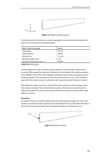
Figure E.2: Blade coordinate system<br />
STRUCTURAL ANALYSIS OF BLADES<br />
The basis mesh for all analyses is created u<strong>sin</strong>g higher-order (parabolic) tetrahedral ele-<br />
ments. The mesh details are tabulated below:<br />
Mesh / element property Value<br />
Total nodes 97144<br />
Total elements 59668<br />
Element size 7.1 mm<br />
Maximum aspect ratio 4.12<br />
Elements with aspect ratio < 3 98.3%<br />
Table E.8: Mesh details<br />
In each analysis the mesh is refined u<strong>sin</strong>g the adaptive h-method, which improves the<br />
accuracy of the analysis by u<strong>sin</strong>g more elements in critical regions. The target accuracy of<br />
the h-method is set to 99%, which indicates intended accuracy in the convergence of the<br />
strain energy norm. The maximum number of iterative loops is set to 5. The simulation<br />
stops when the target accuracy is achieved or the maximum number of loops is reached.<br />
The maximum energy norm error, which indicates the variation in strain energy at com-<br />
mon nodes, is less than 5% for all performed analyses. The low error can be viewed to<br />
represent similarly low stress errors in the model, which indicates a solution with a high<br />
degree of accuracy.<br />
Restraints<br />
The blade is fixed as a cantilever blade by the root of the airfoil, see figure E.3. This cross-<br />
section is considered weaker than the root of the hub junction [5, p. 69], which therefore is<br />
left out of the model. The fixture sets all translational degrees of freedom to zero.<br />
Figure E.3: Model restraints<br />
153