Mise en page 1 - Laboratoire National des Champs Magnétiques ...
Mise en page 1 - Laboratoire National des Champs Magnétiques ...
Mise en page 1 - Laboratoire National des Champs Magnétiques ...

You also want an ePaper? Increase the reach of your titles
YUMPU automatically turns print PDFs into web optimized ePapers that Google loves.
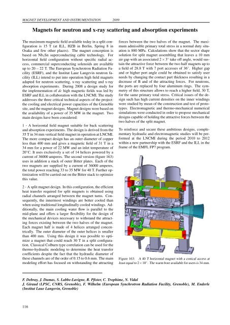
MAGNET DEVELOPMENT AND INSTRUMENTATION 2009Magnets for neutron and x-ray scattering and absorption experim<strong>en</strong>tsThe maximum magnetic field available today in a split configurationis 15 T (at ILL, HZB in Berlin, Spring 8 inOsaka and few other places). The magnet conception isbased on Nb 3 Sn superconducting cable technology. Forhorizontal field configuration without specific radial access,commercial superconducting sol<strong>en</strong>oids are availableup to 20 − 22 T. The European Synchrotron Radiation Facility(ESRF), and the Institut Laue Langevin neutron facility(ILL) int<strong>en</strong>d to put into operation high field magnetsadapted for neutron scattering, x-ray scattering and x-rayabsorption experim<strong>en</strong>ts. During 2008 a <strong>des</strong>ign study forthe implem<strong>en</strong>tation of dc high magnetic fields was led byESRF and ILL in collaboration with the LNCMI. The studyaddresses the three critical technical aspects of the project:the cooling and electrical power capacities of the Gr<strong>en</strong>oblesite, and the magnet <strong>des</strong>igns. Magnet <strong>des</strong>igns were based onthe availability of a power of 35 MW in the magnet. Twomain <strong>des</strong>igns have be<strong>en</strong> considered:1 - A horizontal field magnet suitable for back scatteringand absorption experim<strong>en</strong>ts. The <strong>des</strong>ign is derived from the35 T in 34 mm vertical field magnet in operation at LNCMI.The more compact <strong>des</strong>ign has an outer diameter of copperless than 400 mm and gives a magnetic field of 31 T in a34 mm for a power of 22 MW and an inlet temperature of20 ◦ C. It uses exclusively a set of 14 helices powered by acurr<strong>en</strong>t of 36000 amperes. The second version (figure 163)uses in addition a stack of outer Bitter plates. Each of thetwo magnets are supplied by a curr<strong>en</strong>t of 36000 amperes,the total power reaching 33 to 35 MW for 40 T. Further optimizationwill be carried out on the Bitter stack to optimizethis value.2 - A split magnet <strong>des</strong>ign. In this configuration, the effici<strong>en</strong>theat transfer required for split magnets is obtained usingradial channels arranged betwe<strong>en</strong> the magnet turns. Consequ<strong>en</strong>tly,the innermost windings are better cooled thanwh<strong>en</strong> using traditional longitudinally cooled windings. Additionally,the main cooling water flow is parallel to themid-plane and offers a larger flexibility for the <strong>des</strong>ign ofthe mechanical devices necessary to withstand the attractingforces existing betwe<strong>en</strong> the two halves of the magnet.Each magnet half is made of 4 helices arranged conc<strong>en</strong>trically.The outer diameter of the outer helices is smallerthan 400 mm. Using this <strong>des</strong>ign it was possible to optimizea magnet that could reach 30 T in a split configuration.Classical Colburn type correlation can be used for thethermo-hydraulic modeling to determine the heat transfercoeffici<strong>en</strong>ts <strong>des</strong>pite the fact that the hydraulic diameter ofthese channels are of the order of 0.15 to 0.6 mm. The mainmodeling effort has focused on withstanding the attractingforces betwe<strong>en</strong> the two halves of the magnet. The maximumadmissible primary total stress in a normal duty situationis 880 MPa. Calculations show that the sector shapesolution for split magnet assembling that leaves a 10 mmair gap with an associated 2 × 3 ◦ take off angle, would sustainthe attractive force betwe<strong>en</strong> the two half magnets up toa field of 28.8 T with 7 port accesses of 36 ◦ . Higher gapand or higher port angle could be obtained to satisfy userneeds by changing the contact part thickness resulting in adecrease of B and of the attracting forces. For neutrons,the ports are replaced by four aluminum rings. The symmetryof this structure allows to reach a higher field, 30 T,for the same primary total stress. Critical issues of the <strong>des</strong>ignsuch has high curr<strong>en</strong>t d<strong>en</strong>sities on the inner windingswere studied by mean of the construction and test of prototypes.Electromagnetic and thermo-mechanical numericalsimulations were conducted in order to propose mechanical<strong>des</strong>igns capable of holding the attractive forces betwe<strong>en</strong> thetwo halves of the split magnet.To reinforce and secure these ambitious <strong>des</strong>igns, complem<strong>en</strong>taryhydraulic and electromagnetic studies will be performedat the LNCMI during the period 2010 to 2012within a new partnership with the ESRF and the ILL in theframe of the EMFL FP7 program.Figure 163: A 40 T horizontal magnet with a conical access atleast equal to 2×10 ◦ . The warm bore available for users is 34 mm.F. Debray, J. Dumas, S. Labbe-Lavigne, R. Pfister, C. Trophime, N. VidalJ. Giraud (LPSC, CNRS, Gr<strong>en</strong>oble), F. Wilhelm (European Synchrotron Radiation Facility, Gr<strong>en</strong>oble), M. Enderle(Institut Laue Langevin, Gr<strong>en</strong>oble)116