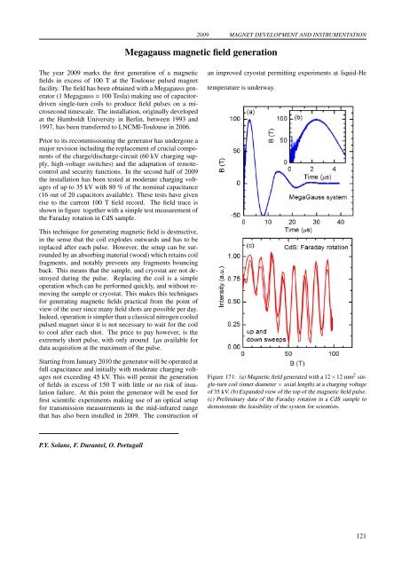
2009 MAGNET DEVELOPMENT AND INSTRUMENTATIONMegagauss magnetic field g<strong>en</strong>erationThe year 2009 marks the first g<strong>en</strong>eration of a magneticfields in excess of 100 T at the Toulouse pulsed magnetfacility. The field has be<strong>en</strong> obtained with a Megagauss g<strong>en</strong>erator(1 Megagauss = 100 Tesla) making use of capacitordriv<strong>en</strong>single-turn coils to produce field pulses on a microsecondtimescale. The installation, originally developedat the Humboldt University in Berlin, betwe<strong>en</strong> 1993 and1997, has be<strong>en</strong> transferred to LNCMI-Toulouse in 2006.an improved cryostat permitting experim<strong>en</strong>ts at liquid-Hetemperature is underway.Prior to its recommissioning the g<strong>en</strong>erator has undergone amajor revision including the replacem<strong>en</strong>t of crucial compon<strong>en</strong>tsof the charge/discharge-circuit (60 kV charging supply,high-voltage switches) and the adaptation of remotecontroland security functions. In the second half of 2009the installation has be<strong>en</strong> tested at moderate charging voltagesof up to 35 kV with 80 % of the nominal capacitance(16 out of 20 capacitors available). These tests have giv<strong>en</strong>rise to the curr<strong>en</strong>t 100 T field record. The field trace isshown in figure together with a simple test measurem<strong>en</strong>t ofthe Faraday rotation in CdS sample.This technique for g<strong>en</strong>erating magnetic field is <strong>des</strong>tructive,in the s<strong>en</strong>se that the coil explo<strong>des</strong> outwards and has to bereplaced after each pulse. However, the setup can be surroundedby an absorbing material (wood) which retains coilfragm<strong>en</strong>ts, and notably prev<strong>en</strong>ts any fragm<strong>en</strong>ts bouncingback. This means that the sample, and cryostat are not <strong>des</strong>troyedduring the pulse. Replacing the coil is a simpleoperation which can be performed quickly, and without removingthe sample or cryostat. This makes this techniquesfor g<strong>en</strong>erating magnetic fields practical from the point ofview of the user since many field shots are possible per day.Indeed, operation is simpler than a classical nitrog<strong>en</strong> cooledpulsed magnet since it is not necessary to wait for the coilto cool after each shot. The price to pay however, is theextremely short pulse, with only around 1µs available fordata acquisition at the maximum of the pulse.Starting from January 2010 the g<strong>en</strong>erator will be operated atfull capacitance and initially with moderate charging voltagesnot exceeding 45 kV. This will permit the g<strong>en</strong>erationof fields in excess of 150 T with little or no risk of insulationfailure. At this point the g<strong>en</strong>erator will be used forfirst sci<strong>en</strong>tific experim<strong>en</strong>ts making use of an optical setupfor transmission measurem<strong>en</strong>ts in the mid-infrared rangethat has also be<strong>en</strong> installed in 2009. The construction ofFigure 171: (a) Magnetic field g<strong>en</strong>erated with a 12×12 mm 2 single-turncoil (inner diameter × axial l<strong>en</strong>gth) at a charging voltageof 35 kV. (b) Expanded view of the top of the magnetic field pulse.(c) Preliminary data of the Faraday rotation in a CdS sample todemonstrate the feasibility of the system for sci<strong>en</strong>tists.P.Y. Solane, F. Durantel, O. Portugall121
MAGNET DEVELOPMENT AND INSTRUMENTATION 2009SEISM: A 60 GHz electron cyclotron resonance (ECR) ion source prototypeLinked to the EURISOL and EURO-ν projects (Designstudies for the second g<strong>en</strong>eration of exotic nuclei acceleratorand the future neutrino factory in Europe), the beta beamproject aims to use the β decay of radioactive ions to produc<strong>en</strong>eutrinos beams. Within the Beta Beam work package(WP4), the ECR task is dedicated to the <strong>des</strong>ign of advancedmagnetic structures to be used in the ECR ion source technology.LPSC has proposed to develop a high frequ<strong>en</strong>cy(60 GHz) pulsed ion source prototype for the beam preparation.A first ion source prototype was <strong>des</strong>igned, basedon a cusp magnetic structure using the polyhelix coil technologyand was named SEISM for Sixty gigahertz Electroncyclotron resonance Ion Source using Megawatt magnets.Here we report progress in the construction of the prototypeand preparation for the first magnetic field measurem<strong>en</strong>tsscheduled in beginning 2010. This work has be<strong>en</strong>carried in the framework of an existing collaboration betwe<strong>en</strong>LPSC and LNCMI.Simulations of the polyhelices have be<strong>en</strong> carried out to finalizethe <strong>des</strong>ign. The temperature field in a coil dep<strong>en</strong>dingon the cooling water flow and on the geometry of the coil insulatorshas be<strong>en</strong> investigated. The geometry and the numbersof insulators (glass fiber) to be positionned betwe<strong>en</strong>each turn of an helice has be<strong>en</strong> specified in order to minimizethe pressure drop, maximize surface cooling and tosustain the 30 tons compression without any copper deformationthat could lead to short-circuit.The maximum electrical power needed is about 6 MW. Awater flow rate of ∼ 30 l/s in the two sets of coils is necessary.Thus, the average coils temperature varies from 80 to180 ◦ C while the peak temperature locally reaches 330 ◦ C.In these conditions, the maximum hoop stress in the coilsis 280 MPa, far below the copper alloy limit of elasticity(360 MPa). At full curr<strong>en</strong>t, the two sets of coils repel eachother with a force of 300 kN. The CAD mechanical <strong>des</strong>ignof the magnetic structure, taking in account all these data,was performed at LPSC. Figure 172 repres<strong>en</strong>ts a cut viewof the source. All mechanical parts will be ready for assemblingin December 2009.Figure 173: On-site implantation scheme for the magnetic fieldmeasurem<strong>en</strong>t at half-int<strong>en</strong>sity. Hydraulic circuit is parallel to M5existing circuit, electrical cables are connected in series with M5magnet.Figure 172: (a) External CAD <strong>des</strong>ign of the ion source prototype,(b) internal view of the curr<strong>en</strong>t and deionized water courses.M5 site was chos<strong>en</strong> as a temporary implantation site for themagnetic field validation at half-curr<strong>en</strong>t. Wh<strong>en</strong> suppliedwith 15 kA, each set of helices (injection set and extractionset) consumes only 0.75 MW of power from the curr<strong>en</strong>tsupply unit. Due to impedance tuning, the prototypeshould be electrically connected in series with an existing10 MW magnet, using flexible power cables. Water flowsof 24 l/s and 22 l/s at a pressure of 20 bars are respectivelyrequired at the injection and extraction. M5 hydraulic circuitwas modified in August 2009 in order to derive about50 l/s from the 150 l/s flow and a parallel hydraulic circuit isnow being installed (figure 173). The incoming water flowwill be controlled with tuneable valves and ultrasonic flowmeters. Hall probes will be mounted on step motor jacks inorder to establish a precise magnetic field map (1mm step).The test b<strong>en</strong>ch is planned to be upgraded with a high voltageplatform and a 28 GHz radiofrequ<strong>en</strong>cy emitter to allowa first characterization of the plasma at the <strong>en</strong>d of year 2010.These activities will be funded within the EURO-ν program(2008 - 2010).C. Trophime, F. Debray, J. Dumas, J. Matera, R. Pfister, N. VidalM. Marie-Jeanne, L. Latrasse, T. Lamy, T. Thuillier, C. Fourel, J. Giraud (LPSC, Gr<strong>en</strong>oble, France)122
- Page 1 and 2:
LABORATOIRE NATIONAL DES CHAMPS MAG
- Page 4 and 5:
TABLE OF CONTENTSPreface 1Carbon Al
- Page 6 and 7:
Coexistence of closed orbit and qua
- Page 8:
2009PrefaceDear Reader,You have bef
- Page 12 and 13:
2009 CARBON ALLOTROPESInvestigation
- Page 14 and 15:
2009 CARBON ALLOTROPESPropagative L
- Page 16 and 17:
2009 CARBON ALLOTROPESEdge fingerpr
- Page 18 and 19:
2009 CARBON ALLOTROPESObservation o
- Page 20 and 21:
2009 CARBON ALLOTROPESImproving gra
- Page 22 and 23:
2009 CARBON ALLOTROPESHow perfect c
- Page 24 and 25:
2009 CARBON ALLOTROPESTuning the el
- Page 26 and 27:
2009 CARBON ALLOTROPESElectric fiel
- Page 28 and 29:
2009 CARBON ALLOTROPESMagnetotransp
- Page 30 and 31:
2009 CARBON ALLOTROPESGraphite from
- Page 32:
2009Two-Dimensional Electron Gas25
- Page 35 and 36:
TWO-DIMENSIONAL ELECTRON GAS 2009Di
- Page 37 and 38:
TWO-DIMENSIONAL ELECTRON GAS 2009Sp
- Page 39 and 40:
TWO-DIMENSIONAL ELECTRON GAS 2009Cr
- Page 41 and 42:
TWO-DIMENSIONAL ELECTRON GAS 2009Re
- Page 43 and 44:
TWO-DIMENSIONAL ELECTRON GAS 2009In
- Page 45 and 46:
TWO-DIMENSIONAL ELECTRON GAS 2009Ho
- Page 47 and 48:
TWO-DIMENSIONAL ELECTRON GAS 2009Te
- Page 50 and 51:
2009 SEMICONDUCTORS AND NANOSTRUCTU
- Page 52 and 53:
2009 SEMICONDUCTORS AND NANOSTRUCTU
- Page 54 and 55:
2009 SEMICONDUCTORS AND NANOSTRUCTU
- Page 56 and 57:
2009 SEMICONDUCTORS AND NANOSTRUCTU
- Page 58 and 59:
2009 SEMICONDUCTORS AND NANOSTRUCTU
- Page 60:
2009Metals, Superconductors and Str
- Page 63 and 64:
METALS, SUPERCONDUCTORS... 2009Anom
- Page 65 and 66:
METALS, SUPERCONDUCTORS... 2009Magn
- Page 67 and 68:
METALS, SUPERCONDUCTORS ... 2009Coe
- Page 69 and 70:
METALS, SUPERCONDUCTORS ... 2009Fie
- Page 71 and 72:
METALS, SUPERCONDUCTORS... 2009High
- Page 73 and 74:
METALS, SUPERCONDUCTORS... 2009Angu
- Page 75 and 76:
METALS, SUPERCONDUCTORS... 2009Magn
- Page 77 and 78: METALS, SUPERCONDUCTORS... 2009Meta
- Page 79 and 80: METALS, SUPERCONDUCTORS... 2009Temp
- Page 81 and 82: METALS, SUPERCONDUCTORS... 200974
- Page 84 and 85: 2009 MAGNETIC SYSTEMSY b 3+ → Er
- Page 86 and 87: 2009 MAGNETIC SYSTEMSMagnetotranspo
- Page 88 and 89: 2009 MAGNETIC SYSTEMSHigh field tor
- Page 90 and 91: 2009 MAGNETIC SYSTEMSNuclear magnet
- Page 92 and 93: 2009 MAGNETIC SYSTEMSStructural ana
- Page 94 and 95: 2009 MAGNETIC SYSTEMSEnhancement ma
- Page 96 and 97: 2009 MAGNETIC SYSTEMSInvestigation
- Page 98 and 99: 2009 MAGNETIC SYSTEMSField-induced
- Page 100 and 101: 2009 MAGNETIC SYSTEMSMagnetic prope
- Page 102: 2009Biology, Chemistry and Soft Mat
- Page 105 and 106: BIOLOGY, CHEMISTRY AND SOFT MATTER
- Page 108 and 109: 2009 APPLIED SUPERCONDUCTIVITYMagne
- Page 110 and 111: 2009 APPLIED SUPERCONDUCTIVITYPhtha
- Page 112: 2009Magneto-Science105
- Page 115 and 116: MAGNETO-SCIENCE 2009Study of the in
- Page 117 and 118: MAGNETO-SCIENCE 2009Magnetohydrodyn
- Page 119 and 120: MAGNETO-SCIENCE 2009112
- Page 122 and 123: 2009 MAGNET DEVELOPMENT AND INSTRUM
- Page 124 and 125: 2009 MAGNET DEVELOPMENT AND INSTRUM
- Page 126 and 127: 2009 MAGNET DEVELOPMENT AND INSTRUM
- Page 130 and 131: 2009 MAGNET DEVELOPMENT AND INSTRUM
- Page 132 and 133: 2009 MAGNET DEVELOPMENT AND INSTRUM
- Page 134 and 135: 2009 MAGNET DEVELOPMENT AND INSTRUM
- Page 136 and 137: 2009 PROPOSALSProposals for Magnet
- Page 138 and 139: 2009 PROPOSALSSpin-Jahn-Teller effe
- Page 140 and 141: 2009 PROPOSALSQuantum Oscillations
- Page 142 and 143: 2009 PROPOSALSThermoelectric tensor
- Page 144 and 145: 2009 PROPOSALSDr. EscoffierCyclotro
- Page 146 and 147: 2009 PROPOSALSHigh field magnetotra
- Page 148 and 149: 2009 THESESPhD Theses 20091. Nanot
- Page 150 and 151: 2009 PUBLICATIONS[21] O. Drachenko,
- Page 152 and 153: 2009 PUBLICATIONS[75] S. Nowak, T.
- Page 154 and 155: Contributors of the LNCMI to the Pr
- Page 156 and 157: Institut Jean Lamour, Nancy : 68Ins
- Page 158 and 159: Lawrence Berkeley National Laborato