2009 MAGNET DEVELOPMENT AND INSTRUMENTATIONA new cooling loop for thermo-hydraulic magnet studiesHeat fluxes <strong>en</strong>countered in high field magnets can be ashigh as 500 W/cm 2 with submillimetric cooling channels.Consequ<strong>en</strong>tly, heat transfers are, together with the materials,a key issue for magnet optimization.The LNCMI has a long term collaboration with the <strong>Laboratoire</strong><strong>des</strong> Ecoulem<strong>en</strong>ts Geophysiques et Industriels (LEGI,CNRS INPG). Most of the experim<strong>en</strong>ts performed were todetermine either the threshold of cavitation in the coolingchannel or the heat transfer coeffici<strong>en</strong>t in a well defined geometry[Reynaud et al., Int. Journal of heat and mass transfer,48, 3197,(2005)]. Nevertheless, the hydraulic coolingloop was limited with a maximum pressure loss of 13 barswhich is roughly half of the pressure loss through our highfield magnets. In addition, high heat fluxes could not bereached on the test section.In 2008 and 2009, LNCMI and LEGI in the frame of theircollaboration have upgraded an existing 40 bars hydrauliccooling loop to study high field magnet thermo-hydraulics.The hydraulic cooling loop (photograph in figure 164) isnow operational for two main kinds of experim<strong>en</strong>ts. One isthe continuation of the precise modelling of heat transfer ina single flat thin channel. Figure 165 shows the related testsession that is now under construction for this purpose. Itis forese<strong>en</strong> to hold a pressure of 40 bars and to characterizethe heat transfer with a velocity up to 40 m/s and heattransfer of at least 100 W/cm 2 , with a variable width of thechannel from 0.2 to 1 mm.Figure 164:assembly.View of the 40 bar hydraulic cooling loop underThanks to the high hydraulic power available on the newhydraulic cooling loop (80 KW instead of 2 KW for the oldhydraulic cooling loop) it is now possible to study directlythe thermo-hydraulics of an <strong>en</strong>tire coil or a group of criticalcoils (helix or Bitter) up to a flow rate of 15 l/s. Thefirst study will concern the flow distribution of the radiallycooled helix that will be used at the c<strong>en</strong>ter of the new highfield 50 mm, 31 T magnet. Consequ<strong>en</strong>tly, an aluminiummodel has be<strong>en</strong> prepared and will be tested at the <strong>en</strong>d of theyear 2009 and it will help to detect possible weak pointsin the very constrained hydraulic <strong>des</strong>ign without using thehigh field facility for this purpose.This work has be<strong>en</strong> partially supported by the ESRF upgradeprogramm and is supported now by the EuromagnetII FP7 program. In this context an <strong>en</strong>gineer, B. Pardo,has be<strong>en</strong> hired in October 2009 and will focus on thermohydraulicmodelling and comparisons with experim<strong>en</strong>taldata. The main goal of this study is to establish a numericalmodel of the radially cooled helix in order to optimizethe geometry of cooling channels. The work will permit to<strong>en</strong>hance the thermo-hydraulics performance of the magnet.Figure 165: A exploded view of the new hydraulic test section tomodel the heat transfers in one channel. Heat flux will be higherthan 100 W/cm, velocity up to 40 m/s and the thickness of thechannel can be changed without dismantling the apparatus. Itis expected to be operational mid 2010. Water flows from leftto right, the thickness of the channel can be varied from 0.2 to0.6 mm. The heaters are located in the red block equipped with aflat heat flux s<strong>en</strong>sor.C. Auternaud, F. Debray, J.Dumas, M. Kamke, J. Matera, R. Pfister, B. Pardo, C. Trophime, E. Verney, N. VidalM. Deleglise (SERAS, CNRS, Gr<strong>en</strong>oble), JP Franc and M. Riondet (LEGI CNRS, INP, UJF, Gr<strong>en</strong>oble)117
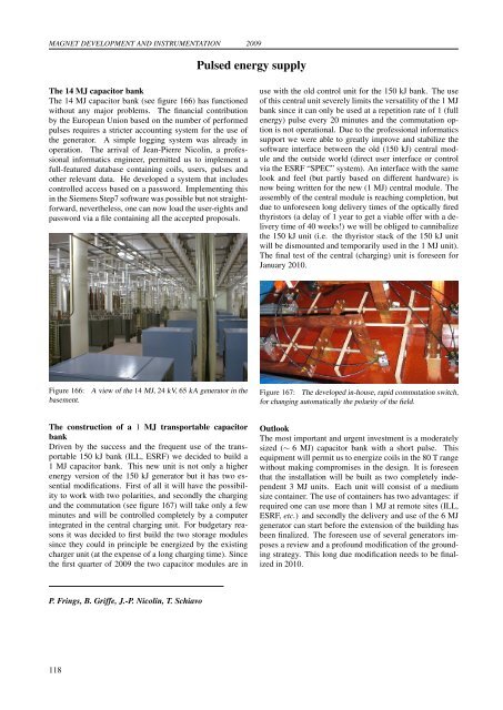
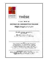
MAGNET DEVELOPMENT AND INSTRUMENTATION 2009Pulsed <strong>en</strong>ergy supplyThe 14 MJ capacitor bankThe 14 MJ capacitor bank (see figure 166) has functionedwithout any major problems. The financial contributionby the European Union based on the number of performedpulses requires a stricter accounting system for the use ofthe g<strong>en</strong>erator. A simple logging system was already inoperation. The arrival of Jean-Pierre Nicolin, a professionalinformatics <strong>en</strong>gineer, permitted us to implem<strong>en</strong>t afull-featured database containing coils, users, pulses andother relevant data. He developed a system that inclu<strong>des</strong>controlled access based on a password. Implem<strong>en</strong>ting thisin the Siem<strong>en</strong>s Step7 software was possible but not straightforward,nevertheless, one can now load the user-rights andpassword via a file containing all the accepted proposals.use with the old control unit for the 150 kJ bank. The useof this c<strong>en</strong>tral unit severely limits the versatility of the 1 MJbank since it can only be used at a repetition rate of 1 (full<strong>en</strong>ergy) pulse every 20 minutes and the commutation optionis not operational. Due to the professional informaticssupport we were able to greatly improve and stabilize thesoftware interface betwe<strong>en</strong> the old (150 kJ) c<strong>en</strong>tral moduleand the outside world (direct user interface or controlvia the ESRF “SPEC” system). An interface with the samelook and feel (but partly based on differ<strong>en</strong>t hardware) isnow being writt<strong>en</strong> for the new (1 MJ) c<strong>en</strong>tral module. Theassembly of the c<strong>en</strong>tral module is reaching completion, butdue to unforese<strong>en</strong> long delivery times of the optically firedthyristors (a delay of 1 year to get a viable offer with a deliverytime of 40 weeks!) we will be obliged to cannibalizethe 150 kJ unit (i.e. the thyristor stack of the 150 kJ unitwill be dismounted and temporarily used in the 1 MJ unit).The final test of the c<strong>en</strong>tral (charging) unit is forese<strong>en</strong> forJanuary 2010.Figure 166:basem<strong>en</strong>t.A view of the 14 MJ, 24 kV, 65 kA g<strong>en</strong>erator in theFigure 167: The developed in-house, rapid commutation switch,for changing automatically the polarity of the field.The construction of a 1 MJ transportable capacitorbankDriv<strong>en</strong> by the success and the frequ<strong>en</strong>t use of the transportable150 kJ bank (ILL, ESRF) we decided to build a1 MJ capacitor bank. This new unit is not only a higher<strong>en</strong>ergy version of the 150 kJ g<strong>en</strong>erator but it has two ess<strong>en</strong>tialmodifications. First of all it will have the possibilityto work with two polarities, and secondly the chargingand the commutation (see figure 167) will take only a fewminutes and will be controlled completely by a computerintegrated in the c<strong>en</strong>tral charging unit. For budgetary reasonsit was decided to first build the two storage modulessince they could in principle be <strong>en</strong>ergized by the existingcharger unit (at the exp<strong>en</strong>se of a long charging time). Sincethe first quarter of 2009 the two capacitor modules are inOutlookThe most important and urg<strong>en</strong>t investm<strong>en</strong>t is a moderatelysized (∼ 6 MJ) capacitor bank with a short pulse. Thisequipm<strong>en</strong>t will permit us to <strong>en</strong>ergize coils in the 80 T rangewithout making compromises in the <strong>des</strong>ign. It is forese<strong>en</strong>that the installation will be built as two completely indep<strong>en</strong>d<strong>en</strong>t3 MJ units. Each unit will consist of a mediumsize container. The use of containers has two advantages: ifrequired one can use more than 1 MJ at remote sites (ILL,ESRF, etc.) and secondly the delivery and use of the 6 MJg<strong>en</strong>erator can start before the ext<strong>en</strong>sion of the building hasbe<strong>en</strong> finalized. The forese<strong>en</strong> use of several g<strong>en</strong>erators imposesa review and a profound modification of the groundingstrategy. This long due modification needs to be finalizedin 2010.P. Frings, B. Griffe, J.-P. Nicolin, T. Schiavo118
- Page 1 and 2:
LABORATOIRE NATIONAL DES CHAMPS MAG
- Page 4 and 5:
TABLE OF CONTENTSPreface 1Carbon Al
- Page 6 and 7:
Coexistence of closed orbit and qua
- Page 8:
2009PrefaceDear Reader,You have bef
- Page 12 and 13:
2009 CARBON ALLOTROPESInvestigation
- Page 14 and 15:
2009 CARBON ALLOTROPESPropagative L
- Page 16 and 17:
2009 CARBON ALLOTROPESEdge fingerpr
- Page 18 and 19:
2009 CARBON ALLOTROPESObservation o
- Page 20 and 21:
2009 CARBON ALLOTROPESImproving gra
- Page 22 and 23:
2009 CARBON ALLOTROPESHow perfect c
- Page 24 and 25:
2009 CARBON ALLOTROPESTuning the el
- Page 26 and 27:
2009 CARBON ALLOTROPESElectric fiel
- Page 28 and 29:
2009 CARBON ALLOTROPESMagnetotransp
- Page 30 and 31:
2009 CARBON ALLOTROPESGraphite from
- Page 32:
2009Two-Dimensional Electron Gas25
- Page 35 and 36:
TWO-DIMENSIONAL ELECTRON GAS 2009Di
- Page 37 and 38:
TWO-DIMENSIONAL ELECTRON GAS 2009Sp
- Page 39 and 40:
TWO-DIMENSIONAL ELECTRON GAS 2009Cr
- Page 41 and 42:
TWO-DIMENSIONAL ELECTRON GAS 2009Re
- Page 43 and 44:
TWO-DIMENSIONAL ELECTRON GAS 2009In
- Page 45 and 46:
TWO-DIMENSIONAL ELECTRON GAS 2009Ho
- Page 47 and 48:
TWO-DIMENSIONAL ELECTRON GAS 2009Te
- Page 50 and 51:
2009 SEMICONDUCTORS AND NANOSTRUCTU
- Page 52 and 53:
2009 SEMICONDUCTORS AND NANOSTRUCTU
- Page 54 and 55:
2009 SEMICONDUCTORS AND NANOSTRUCTU
- Page 56 and 57:
2009 SEMICONDUCTORS AND NANOSTRUCTU
- Page 58 and 59:
2009 SEMICONDUCTORS AND NANOSTRUCTU
- Page 60:
2009Metals, Superconductors and Str
- Page 63 and 64:
METALS, SUPERCONDUCTORS... 2009Anom
- Page 65 and 66:
METALS, SUPERCONDUCTORS... 2009Magn
- Page 67 and 68:
METALS, SUPERCONDUCTORS ... 2009Coe
- Page 69 and 70:
METALS, SUPERCONDUCTORS ... 2009Fie
- Page 71 and 72:
METALS, SUPERCONDUCTORS... 2009High
- Page 73 and 74: METALS, SUPERCONDUCTORS... 2009Angu
- Page 75 and 76: METALS, SUPERCONDUCTORS... 2009Magn
- Page 77 and 78: METALS, SUPERCONDUCTORS... 2009Meta
- Page 79 and 80: METALS, SUPERCONDUCTORS... 2009Temp
- Page 81 and 82: METALS, SUPERCONDUCTORS... 200974
- Page 84 and 85: 2009 MAGNETIC SYSTEMSY b 3+ → Er
- Page 86 and 87: 2009 MAGNETIC SYSTEMSMagnetotranspo
- Page 88 and 89: 2009 MAGNETIC SYSTEMSHigh field tor
- Page 90 and 91: 2009 MAGNETIC SYSTEMSNuclear magnet
- Page 92 and 93: 2009 MAGNETIC SYSTEMSStructural ana
- Page 94 and 95: 2009 MAGNETIC SYSTEMSEnhancement ma
- Page 96 and 97: 2009 MAGNETIC SYSTEMSInvestigation
- Page 98 and 99: 2009 MAGNETIC SYSTEMSField-induced
- Page 100 and 101: 2009 MAGNETIC SYSTEMSMagnetic prope
- Page 102: 2009Biology, Chemistry and Soft Mat
- Page 105 and 106: BIOLOGY, CHEMISTRY AND SOFT MATTER
- Page 108 and 109: 2009 APPLIED SUPERCONDUCTIVITYMagne
- Page 110 and 111: 2009 APPLIED SUPERCONDUCTIVITYPhtha
- Page 112: 2009Magneto-Science105
- Page 115 and 116: MAGNETO-SCIENCE 2009Study of the in
- Page 117 and 118: MAGNETO-SCIENCE 2009Magnetohydrodyn
- Page 119 and 120: MAGNETO-SCIENCE 2009112
- Page 122 and 123: 2009 MAGNET DEVELOPMENT AND INSTRUM
- Page 126 and 127: 2009 MAGNET DEVELOPMENT AND INSTRUM
- Page 128 and 129: 2009 MAGNET DEVELOPMENT AND INSTRUM
- Page 130 and 131: 2009 MAGNET DEVELOPMENT AND INSTRUM
- Page 132 and 133: 2009 MAGNET DEVELOPMENT AND INSTRUM
- Page 134 and 135: 2009 MAGNET DEVELOPMENT AND INSTRUM
- Page 136 and 137: 2009 PROPOSALSProposals for Magnet
- Page 138 and 139: 2009 PROPOSALSSpin-Jahn-Teller effe
- Page 140 and 141: 2009 PROPOSALSQuantum Oscillations
- Page 142 and 143: 2009 PROPOSALSThermoelectric tensor
- Page 144 and 145: 2009 PROPOSALSDr. EscoffierCyclotro
- Page 146 and 147: 2009 PROPOSALSHigh field magnetotra
- Page 148 and 149: 2009 THESESPhD Theses 20091. Nanot
- Page 150 and 151: 2009 PUBLICATIONS[21] O. Drachenko,
- Page 152 and 153: 2009 PUBLICATIONS[75] S. Nowak, T.
- Page 154 and 155: Contributors of the LNCMI to the Pr
- Page 156 and 157: Institut Jean Lamour, Nancy : 68Ins
- Page 158 and 159: Lawrence Berkeley National Laborato