GUIDE WAVE ANALYSIS AND FORECASTING - WMO
GUIDE WAVE ANALYSIS AND FORECASTING - WMO
GUIDE WAVE ANALYSIS AND FORECASTING - WMO

You also want an ePaper? Increase the reach of your titles
YUMPU automatically turns print PDFs into web optimized ePapers that Google loves.
ange of directions. Also, waves at different frequencies<br />
will propagate at different speeds. Thus, from a point<br />
source, each component of the spectrum E(f,θ) can be<br />
propagated in the direction θ with a speed c g(f,θ).<br />
3.3.1 Angular spreading<br />
It is often assumed that the directional part of the windwave<br />
distribution has a cos 2 (θ − ψ) form where ψ is the<br />
predominant direction of the waves and θ is the direction<br />
of the spectral component concerned. Most of the<br />
energy is propagated in the mean direction of the sea.<br />
At deviating angles, less energy is transported<br />
and, for all practical purposes, the energy propagated<br />
at right angles to the mean direction is negligible. There<br />
is considerable evidence indicating that the spread<br />
is dependent on the lengths of waves. Several such<br />
formulations for the directional distribution based<br />
on observations have been given. Using the form<br />
cos 2s (θ − ψ)/2, Mitsuyasu et al. (1975) and<br />
Hasselmann et al. (1980) give functional forms for s<br />
which are dependent on the ratio of frequency to peak<br />
frequency. These indicate the narrowest spread at the<br />
peak of the spectrum, with widening at both lower and<br />
higher frequencies. However, there is still uncertainty<br />
with respect to the real functional form of the s para-<br />
<strong>WAVE</strong> GENERATION <strong>AND</strong> DECAY 37<br />
2 5 2 5 2 5 2 5 2 5<br />
10 3<br />
10 4<br />
10 5<br />
10 10 2<br />
H c * versus X*<br />
H c * versus t*<br />
T c * versus X*<br />
T c * versus t*<br />
t* and X*<br />
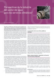
Figure 3.1 — Basic diagram for manual wave forecasting. The curves are drawn for non-dimensional parameters<br />
(H c* = gH c/u 2 ; T c* = gT c/u) (derived from Gröen and Dorrestein, 1976)<br />
H c * T c *<br />
0,24<br />
2<br />
-<br />
10 -1<br />
10 -2<br />
10 -3<br />
meter in simple sea states (e.g. wind-sea generation and<br />
long swells). This is due to the fact that different directional<br />
wave instruments located very close to one<br />
another give widely different results (see for example,<br />
Allender et al., 1989).<br />
Waves which have left the generating area (i.e.<br />
swell) are reduced by the angular spreading. Numerical<br />
models automatically take care of this by splitting the<br />
spectrum into components and propagating each of the<br />
components independently. Manual methods require<br />
more action by the operator. Angular spreading and<br />
dispersion factors must be applied.<br />
As illustrated in Figure 3.2, a point P will receive<br />
wave energy from points all along the front of the fetch.<br />
It is possible to compute the sum of all the contributions.<br />
For a cosine-squared distribution of energy at the fetch<br />
front, results are shown in Figure 3.3. At any fixed<br />
frequency, the curved lines in this diagram represent the<br />
percentages of the wave energy from the fetch front<br />
which reach there. These are the angular spreading<br />
factors. The spatial coordinates are expressed in terms of<br />
the width AB of the fetch area. For example, at a<br />
distance of 2.5 AB along the predominant swell<br />
direction, the wave energy has decreased to about 25 per<br />
cent of the energy per unit area which was present at the<br />
fetch front AB. The reduction in wave height due to<br />
5<br />
2<br />
5<br />
2<br />
10<br />
6,28<br />
1