GUIDE WAVE ANALYSIS AND FORECASTING - WMO
GUIDE WAVE ANALYSIS AND FORECASTING - WMO
GUIDE WAVE ANALYSIS AND FORECASTING - WMO

You also want an ePaper? Increase the reach of your titles
YUMPU automatically turns print PDFs into web optimized ePapers that Google loves.
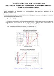
Figure 3.7 —<br />
Structure of spectral energy growth.<br />
The upper curves show the components<br />
S nl, S in, and S ds. The lower<br />
curves are the frequency spectrum<br />
E(f), and the total growth curve S<br />
Energy density (E) Rate of growth (S)<br />
growth at a given frequency is dominated by the nonlinear<br />
wave-wave interaction. As a wind sea develops (or<br />
as we move out along a fetch) the peak frequency<br />
decreases. A given frequency, f e, will first be well below<br />
a peak frequency, resulting in a small amount of growth<br />
from the wind forcing, some non-linear interactions, and<br />
a little dissipation. As the peak becomes lower and<br />
approaches f e, the energy at f e comes under the influence<br />
of a large input from non-linear interactions. This can be<br />
seen in Figures 3.5 and 3.7 in the large positive region of<br />
S or S nl just below the peak. As the peak falls below f e<br />
this input reverses, and an equilibrium is reached<br />
(known as the saturation state). Figure 3.6 illustrates the<br />
development along a fetch of the energy density at such<br />
a given frequency f e.<br />
Although the non-linear theory can be expressed,<br />
as in Equation 3.4, the evaluation is a problem. The<br />
integral in Equation 3.4 requires a great deal of<br />
computer time, and it is not practical to include it in<br />
this form in operational wave models. Some wave<br />
models use the similarity of spectral shape, which is a<br />
manifestation of this process, to derive an algorithm so<br />
that the integral calculation can be bypassed. Having<br />
established the total energy in the wind-sea spectrum,<br />
these models will force it into a pre-defined spectral<br />
shape. Alternatively, it is now possible to use integration<br />
techniques and simplifications which allow a<br />
reasonable approximation to the integral to be evaluated<br />
(see the discrete interaction approximation (DIA)<br />
of Hasselmann and Hasselmann, 1981, Hasselmann<br />
and Hasselmann, 1985, and Hasselmann et. al., 1985;<br />
or the two-scale approximation (TSA) of Resio et al.,<br />
1992). These efficient computations of the non-linear<br />
<strong>WAVE</strong> GENERATION <strong>AND</strong> DECAY 41<br />
S n1<br />
S<br />
S in<br />
E (f)<br />
S ds<br />
transfer integral made it possible to develop third<br />
generation wave models which compute the non-linear<br />
source term explicitly without a prescribed shape for<br />
the wind-sea spectrum.<br />
Resonant weakly non-linear wave-wave interactions<br />
are only one facet of the non-linear problem.<br />
When the slopes of the waves become steeper, and the<br />
non-linearities stronger, modellers are forced to resort to<br />
weaker theories and empirical forms to represent<br />
processes such as wave breaking. These aspects have<br />
been mentioned in Section 3.4.<br />
3.6 General notes on application<br />
The overall source term is S = S in + S ds + S nl. Ignoring<br />
the directional characteristics (i.e. looking only at the<br />
frequency dependence), we can construct a diagram for<br />
S such as Figure 3.7. This gives us an idea of the relative<br />
importance of the various processes at different frequencies.<br />
For example, we can see that the non-linear transfer<br />
is the dominant growth agent at frequencies near the<br />
spectral peak. Also, for the mid-frequency range (from<br />
the peak to about twice the peak frequency) the growth<br />
is dominated by the direct input from the atmosphere.<br />
The non-linear term relocates this energy mostly to the<br />
lower frequency range. The dissipation term, so far as is<br />
known, operates primarily on the mid- and highfrequency<br />
ranges.<br />
The development of a frequency spectrum along a<br />
fetch is illustrated in Figure 3.8 with a set of spectra<br />
measured during the JONSWAP experiment. The downshift<br />
in peak frequency and the overshoot effect at each<br />
frequency are evident.<br />
f<br />
f