GUIDE WAVE ANALYSIS AND FORECASTING - WMO
GUIDE WAVE ANALYSIS AND FORECASTING - WMO
GUIDE WAVE ANALYSIS AND FORECASTING - WMO

You also want an ePaper? Increase the reach of your titles
YUMPU automatically turns print PDFs into web optimized ePapers that Google loves.
82<br />
in the direction of wave propagation. Any decrease in cg is therefore accompanied by a corresponding increase in<br />
wave height (and vice versa, any increase in cg by a<br />
decrease in wave height). This is readily illustrated with<br />
a wave perpendicular to a straight coast. Its wave height<br />
can be determined from this conservation of energy<br />
transport (i.e. assuming no dissipation), with:<br />
H 2 =<br />
(7.3)<br />
where H is the wave height and the subscripts 1 and 2<br />
refer to any two different locations along the (straight)<br />
path of the wave.<br />
The inclusion of shoaling in an Eulerian discrete<br />
spectral wave model as described in Section 5.3 is relatively<br />
simple. Only the determination of c g,x and c g,y in<br />
Equation 5.4 needs to be adapted as described above by<br />
c g = βc phase.<br />
7.3 Refraction<br />
In addition to changing the wave height, the change in<br />
phase velocity will turn the wave direction (when the<br />
crests are not parallel to the bottom contours). This is<br />
readily illustrated with a long-crested harmonic wave<br />
approaching a straight coastline at an angle. In this case<br />
the crest of the wave is infinitely long in deep water.<br />
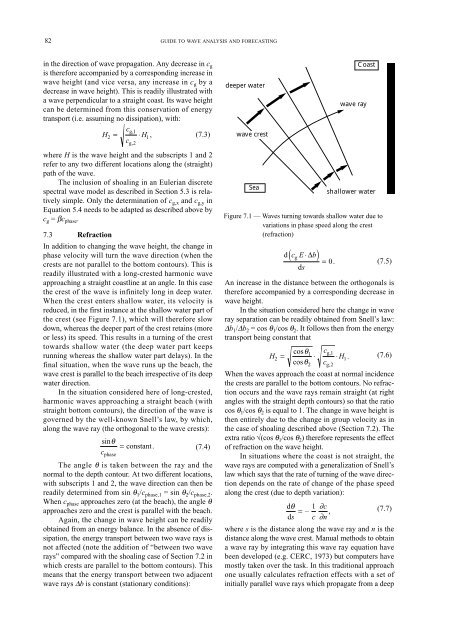
When the crest enters shallow water, its velocity is<br />
reduced, in the first instance at the shallow water part of<br />
the crest (see Figure 7.1), which will therefore slow<br />
down, whereas the deeper part of the crest retains (more<br />
or less) its speed. This results in a turning of the crest<br />
towards shallow water (the deep water part keeps<br />
running whereas the shallow water part delays). In the<br />
final situation, when the wave runs up the beach, the<br />
wave crest is parallel to the beach irrespective of its deep<br />
water direction.<br />
In the situation considered here of long-crested,<br />
harmonic waves approaching a straight beach (with<br />
straight bottom contours), the direction of the wave is<br />
governed by the well-known Snell’s law, by which,<br />
along the wave ray (the orthogonal to the wave crests):<br />
sinθ<br />
c g,1<br />
c g,2<br />
⋅H 1 ,<br />
= constant.<br />
(7.4)<br />
cphase The angle θ is taken between the ray and the<br />
normal to the depth contour. At two different locations,<br />
with subscripts 1 and 2, the wave direction can then be<br />
readily determined from sin θ1/cphase,1 = sin θ2/cphase,2. When cphase approaches zero (at the beach), the angle θ<br />
approaches zero and the crest is parallel with the beach.<br />
Again, the change in wave height can be readily<br />
obtained from an energy balance. In the absence of dissipation,<br />
the energy transport between two wave rays is<br />
not affected (note the addition of “between two wave<br />
rays” compared with the shoaling case of Section 7.2 in<br />
which crests are parallel to the bottom contours). This<br />
means that the energy transport between two adjacent<br />
wave rays ∆b is constant (stationary conditions):<br />
<strong>GUIDE</strong> TO <strong>WAVE</strong> <strong>ANALYSIS</strong> <strong>AND</strong> <strong>FORECASTING</strong><br />
deeper water<br />
wave crest<br />
Sea<br />
d( cg E ⋅∆b)<br />
= 0.<br />
ds<br />
(7.5)<br />
An increase in the distance between the orthogonals is<br />
therefore accompanied by a corresponding decrease in<br />
wave height.<br />
In the situation considered here the change in wave<br />
ray separation can be readily obtained from Snell’s law:<br />
∆b1/∆b2 = cos θ1/cos θ2. It follows then from the energy<br />
transport being constant that<br />
cosθ c 1 g,1<br />
H (7.6)<br />
2 = ⋅ ⋅H1 .<br />
cosθ2 cg,2 When the waves approach the coast at normal incidence<br />
the crests are parallel to the bottom contours. No refraction<br />
occurs and the wave rays remain straight (at right<br />
angles with the straight depth contours) so that the ratio<br />
cos θ1/cos θ2 is equal to 1. The change in wave height is<br />
then entirely due to the change in group velocity as in<br />
the case of shoaling described above (Section 7.2). The<br />
extra ratio √(cos θ1/cos θ2) therefore represents the effect<br />
of refraction on the wave height.<br />
In situations where the coast is not straight, the<br />
wave rays are computed with a generalization of Snell’s<br />
law which says that the rate of turning of the wave direction<br />
depends on the rate of change of the phase speed<br />
along the crest (due to depth variation):<br />
dθ 1<br />
= –<br />
ds c<br />
∂c<br />
∂n ,<br />
Coast<br />
wave ray<br />
shallower water<br />
Figure 7.1 — Waves turning towards shallow water due to<br />
variations in phase speed along the crest<br />
(refraction)<br />
(7.7)<br />
where s is the distance along the wave ray and n is the<br />
distance along the wave crest. Manual methods to obtain<br />
a wave ray by integrating this wave ray equation have<br />
been developed (e.g. CERC, 1973) but computers have<br />
mostly taken over the task. In this traditional approach<br />
one usually calculates refraction effects with a set of<br />
initially parallel wave rays which propagate from a deep