Installation Manual
Installation Manual
Installation Manual

You also want an ePaper? Increase the reach of your titles
YUMPU automatically turns print PDFs into web optimized ePapers that Google loves.
Chapter 4 ������������ ��� �������<br />
4.7.3 External connections<br />
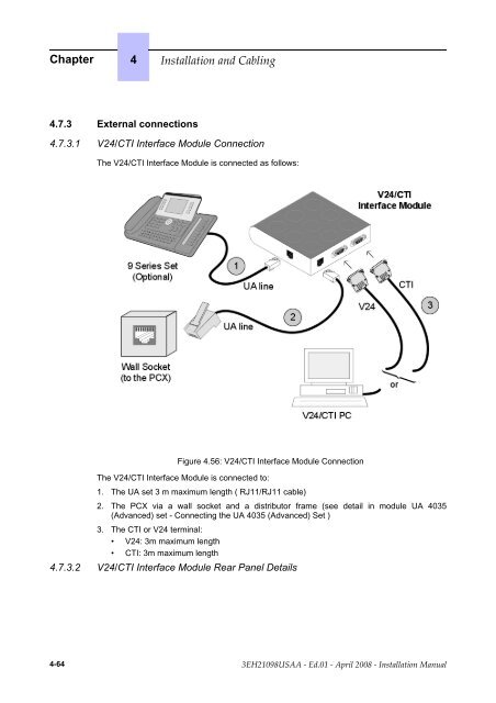
4.7.3.1 V24/CTI Interface Module Connection<br />
The V24/CTI Interface Module is connected as follows:<br />
_<br />
_<br />
_<br />
c<br />
h<br />
a<br />
n<br />
g<br />
e<br />
-<br />
b<br />
e<br />
g<br />
i<br />
n<br />
_<br />
_<br />
_<br />
_<br />
_<br />
_<br />
c<br />
h<br />
a<br />
n<br />
g<br />
e<br />
-<br />
e<br />
n<br />
d<br />
_<br />
_<br />
_<br />
Figure 4.56: V24/CTI Interface Module Connection<br />
The V24/CTI Interface Module is connected to:<br />
1. The UA set 3 m maximum length ( RJ11/RJ11 cable)<br />
2. The PCX via a wall socket and a distributor frame (see detail in module UA 4035<br />
(Advanced) set - Connecting the UA 4035 (Advanced) Set )<br />
3. The CTI or V24 terminal:<br />
• V24: 3m maximum length<br />
• CTI: 3m maximum length<br />
4.7.3.2 V24/CTI Interface Module Rear Panel Details<br />
_<br />
_<br />
_<br />
c<br />
h<br />
a<br />
n<br />
g<br />
e<br />
-<br />
b<br />
e<br />
g<br />
i<br />
n<br />
_<br />
_<br />
_<br />
4-64 ������������ � ����� � ����� ���� � ������������ ������