Installation Manual
Installation Manual
Installation Manual

You also want an ePaper? Increase the reach of your titles
YUMPU automatically turns print PDFs into web optimized ePapers that Google loves.
_<br />
_<br />
_<br />
c<br />
h<br />
a<br />
n<br />
g<br />
e<br />
-<br />
e<br />
n<br />
d<br />
_<br />
_<br />
_<br />
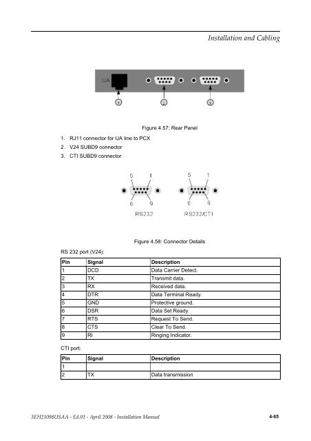
1. RJ11 connector for UA line to PCX<br />
2. V24 SUBD9 connector<br />
3. CTI SUBD9 connector<br />
_<br />
_<br />
_<br />
c<br />
h<br />
a<br />
n<br />
g<br />
e<br />
-<br />
b<br />
e<br />
g<br />
i<br />
n<br />
_<br />
_<br />
_<br />
_<br />
_<br />
_<br />
c<br />
h<br />
a<br />
n<br />
g<br />
e<br />
-<br />
e<br />
n<br />
d<br />
_<br />
_<br />
_<br />
RS 232 port (V24):<br />
Figure 4.57: Rear Panel<br />
Figure 4.58: Connector Details<br />
Pin Signal Description<br />
1 DCD Data Carrier Detect.<br />
2 TX Transmit data.<br />
3 RX Received data.<br />
4 DTR Data Terminal Ready.<br />
5 GND Protective ground.<br />
6 DSR Data Set Ready.<br />
7 RTS Request To Send.<br />
8 CTS Clear To Send.<br />
9 RI Ringing Indicator.<br />
CTI port:<br />
Pin Signal Description<br />
1<br />
2 TX Data transmission<br />
������������ ��� �������<br />
������������ � ����� � ����� ���� � ������������ ������ 4-65