A Semi-Implicit, Three-Dimensional Model for Estuarine ... - USGS
A Semi-Implicit, Three-Dimensional Model for Estuarine ... - USGS
A Semi-Implicit, Three-Dimensional Model for Estuarine ... - USGS

You also want an ePaper? Increase the reach of your titles
YUMPU automatically turns print PDFs into web optimized ePapers that Google loves.
5. Numerical Experiments 95<br />
solution to the fully nonlinear test problem is well known from these past model applications; the convergence characteristics of<br />
these previously tested models vary widely, depending on their numerical accuracy.<br />
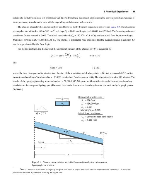
The channel characteristics and initial flow conditions <strong>for</strong> the hydrograph experiment are given in figure 5.1. The channel is<br />
rectangular; top width B = 100 ft (30.5 m), 45 bed slope S 0 = 0.001, and length L = 150,000 ft (45,720 m). The Manning resistance<br />
coefficient <strong>for</strong> the channel is 0.045. The initial steady flow is Q 0 = 250 ft 3 /s (7.1 m 3 /s), and the initial flow depth according to<br />
Manning’s <strong>for</strong>mula is H 0 = 1.688 ft (0.51 m). The channel is considered wide enough so that the hydraulic radius in equation 4.3<br />
can be approximated by the flow depth.<br />
and<br />
For the test problem, the discharge at the upstream boundary of the channel (x = 0) is described by<br />
750<br />
Qt () = 250 + -------- ⎛1– cos-----<br />
πt⎞<br />
0 < t < 150<br />
π ⎝ 75⎠<br />
Qt () = 250<br />
t ≥ 150 ,<br />
where the time t is expressed in minutes from the start of the simulation and discharge is in cubic feet per second (ft 3 /s). At the<br />
downstream boundary of the channel (x = 150,000), the depth of flow is constant at H 0. The simulation is run <strong>for</strong> 500 minutes. The<br />
results of the hydrograph routing are examined at x = 50,000 ft (15,240 m) to avoid any effect from the downstream boundary<br />
condition on the computed hydrograph. (The water level at the downstream boundary does not rise until the hydrograph passes<br />
50,000 ft.)<br />
Q = Q (t )<br />
Datum<br />
x<br />
1<br />
B<br />
H 0<br />
Δ<br />
Q 0<br />
1 ⁄ S0 L<br />
Channel characteristics<br />
B = 100 feet<br />
L = 150,000 feet<br />
S 0 = 0.001<br />
Manning’s n = 0.045<br />
Initial flow conditions<br />
Q 0 = 250 cubic feet per second<br />
H 0 = 1.688 feet<br />
Δ<br />
Q = Q 0<br />
Figure 5.1. Channel characteristics and initial flow conditions <strong>for</strong> the 1-dimensional<br />
hydrograph test problem.<br />
45 The 1-D numerical experiments, as originally designed, were posed in English units; these units are adopted here <strong>for</strong> consistency. The metric unit<br />
conversions are shown in parentheses following the English units.