Puritan Bennett 560 Ventilator User's Manual - Covidien
Puritan Bennett 560 Ventilator User's Manual - Covidien
Puritan Bennett 560 Ventilator User's Manual - Covidien

You also want an ePaper? Increase the reach of your titles
YUMPU automatically turns print PDFs into web optimized ePapers that Google loves.
Safety Information<br />
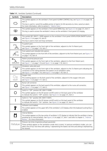
Table 1-1. <strong>Ventilator</strong> Symbols (Continued)<br />
Symbols Descriptions<br />
O<br />
I<br />
This symbol appears on the ventilator’s front panel ALARM CONTROL key; see Figure 2-3 on page 2-6,<br />
item 3. (See my notes, to the left and below, in red).<br />
This key is used to: cancel the audible portion of alarms for 60 seconds at a time; cancel an alarm.<br />
For more information, refer to section E, “Alarms Tests.”<br />
This symbol appears on the ventilator’s front panel MENU key; see Figure 2-2 on page 2-5, item 7.<br />
This key is used to access the ventilator’s menus via the ventilator’s front panel LCD display.<br />
This symbol (IEC 60417– 5009) appears on the ventilator’s front panel VENTILATION ON/OFF button;<br />
see Figure 2-3 on page 2-6, item 8.<br />
This key is used to Start and Stop ventilation.<br />
To patient port.<br />
This symbol appears on the front right of the ventilator, adjacent to the To Patient port;<br />
see Figure 1-1 on page 1-16, item 1.<br />
From patient-port (double-limb option).<br />
This symbol appears on the front-left of the ventilator, adjacent to the From Patient port; see Figure 1-1<br />
on page 1-16, item 4.<br />
Patient proximal pressure port.<br />
This symbol appears on the front right of the ventilator, adjacent to the From Patient port;<br />
see Figure 1-1 on page 1-16 and Figure 1-4 on page 1-18, item 3.<br />
Exhalation valve pilot port.<br />
This symbol appears on the front right of the ventilator, adjacent to the To Patient port indicating the<br />
connection of the tubing between the patient circuit exhalation valve;<br />
see Figure 1-1 on page 1-16, and Figure 1-4 on page 1-18, item 3.<br />
Oxygen inlet.<br />
This marking appears on the back panel of the ventilator, adjacent to the oxygen inlet port;<br />
see Figure 1-3 on page 1-17, item 2.<br />
Nurse Call connector.<br />
This symbol appears on the back panel of the ventilator, adjacent to the nurse call connector;<br />
see Figure 1-3 on page 1-17, item 2.<br />
Switch in “Off” position (IEC 60417-5008).<br />
This symbol appears on the I/O (power on/off) switch on the back panel of the ventilator<br />
to indicate the switch’s “Off” position. See Figure 2-2 on page 2-5, item 2.<br />
Switch in “On” position (IEC 60417-5007).<br />
This symbol appears on the I/O (power on/off) switch on the back panel of the ventilator<br />
to indicate the switch’s “On” position. See Figure 2-2 on page 2-5, item 2.<br />
Software Lock Enabled.<br />
This symbol appears on the upper-left of the ventilator’s LCD display when the keyboard Locking Key is<br />
enabled.<br />
Internal Battery.<br />
This symbol appears on the top-center of ventilator’s LCD display to indicate that the ventilator is being<br />
powered by its internal battery. See Figure 2-4 on page 2-7, item 1 and refer to chapter 6, “Internal<br />
Battery”, for more information.<br />
Pressure rise times (inspiratory phase) parameter.<br />
These symbols appear on the ventilation mode menu screens. In pressure ventilation modes, you can<br />
select one of four rise times with setting 1 representing the fastest rise time and setting 4 representing<br />
the slowest.<br />
1-12 User’s <strong>Manual</strong>