Puritan Bennett 560 Ventilator User's Manual - Covidien
Puritan Bennett 560 Ventilator User's Manual - Covidien
Puritan Bennett 560 Ventilator User's Manual - Covidien

Create successful ePaper yourself
Turn your PDF publications into a flip-book with our unique Google optimized e-Paper software.
Installation and Assembly<br />
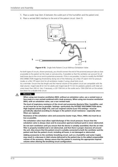
5. Place a water trap (item 3) between the outlet port of the humidifier and the patient end.<br />
6. Place a vented (NIV) interface to the end of the patient circuit. (item 5)<br />
5<br />
Figure 4-10. Single limb Patient Circuit Without Exhalation Valve<br />
For both types of circuits, shown previously, you should connect the end of the proximal pressure tube as close<br />
as possible to the patient (at the mask or cannula entry, if possible) so that the ventilator can account for all<br />
load losses due to the circuit and its potential accessories. If this is not possible, it is best to modify the PATIENT<br />
DISCONNECTION triggering threshold by doing one of the following: set a Max VTI alarm limit for pressure<br />
modes or a Min VTE alarm limit for all ventilation modes if using a dual limb circuit.<br />
As a reminder: Ensure that the length and the internal volume of the patient circuit are compatible with the<br />
tidal volume: ringed tube Ø 22 mm for adults and ringed tube Ø 15 mm for pediatric patients with tidal volumes<br />
lower than 200 ml. Use, if necessary, a 22F-15M link on the outlet and a 15M-22M link on the exhalation<br />
block for a double limb circuit.<br />
Warning<br />
When using non-invasive ventilation (NIV), without an exhalation valve, use a vented nose or<br />
face mask or a non vented combined with a leak accessory. When using non-invasive ventilation<br />
(NIV), with an exhalation valve, use a non vented mask.<br />
The level of inspiratory resistance of the circuit and accessories (bacteria filter, humidifier, and<br />
so on) must be as low as possible. Settings—particularly the PATIENT DISCONNECTION alarm,<br />
High inspired volume (High VTI), and Low inspired volume (Low VTI) settings—must be<br />
periodically adjusted according to changes in the patient circuit resistance—especially when<br />
filters are replaced.<br />
Resistance of the exhalation valve and accessories (water traps, filters, HMEs etc) must be as<br />
low as possible.<br />
The exhalation valve must allow rapid discharge of the circuit pressure. Ensure that the<br />
exhalation valve is always clean and its evacuation aperture (exhaust port) is never obstructed.<br />
Do not start ventilation until you ensure that the device is suitably assembled, that the air inlet<br />
filter is properly installed and is not obstructed, and that there is proper clearance all around<br />
the unit. Also ensure that the patient circuit is suitably connected to both the ventilator and the<br />
patient and that the patient circuit, including all hoses, is not damaged or obstructed.<br />
Adding accessories to the ventilator breathing circuit, such as a humidifier and water trap(s),<br />
may result in a decrease in tidal volume delivered to the patient due to the added compressible<br />
volume of the accessory. Always assure that the patient is receiving the appropriate inspired<br />
volume when altering the breathing circuit configuration.<br />
4-10 User’s <strong>Manual</strong><br />
4<br />
1<br />
2<br />
3