Manual T*SOL basic 5.0 - Valentin Software
Manual T*SOL basic 5.0 - Valentin Software
Manual T*SOL basic 5.0 - Valentin Software

You also want an ePaper? Increase the reach of your titles
YUMPU automatically turns print PDFs into web optimized ePapers that Google loves.
User <strong>Manual</strong> <strong>T*SOL</strong> 7 System Definition<br />
The system components are listed on the Components page. These vary depending on the selected<br />
system:<br />
Solar Loop, Collector Loop Connection, Auxiliary Heating, Tank, Swimming Pool and External Heat<br />
Exchanger, and Solar Loop Heat Exchanger<br />
The Control page is particularly important. Here, depending on the selected system schematic, you set<br />
the DHW circuit priority, the Anti-Legionnaire's Switch(see chapter 10.11.5), and the stratification.<br />
The Savings page contains parameters for calculating pollutants and fuel.<br />
You can define a reference system which can be used to carry out the emissions calculation. The setting<br />
in the example shown will calculate the savings and the emissions reduction with an efficiency of 70 % in<br />
the simulation compared to the oil boiler otherwise used.<br />
7.1.1 Two Collector Loops<br />
System Definition > System > Components > Solar Loop<br />
The option of Two Collector Loops has been integrated in systems A1, A2, A5, A12, A17, and A18. It is now<br />
possible to define and simulate two collector loops independently of one another there.<br />
Ł How to proceed:<br />
1. Selects a suitable system (A1, A2, or A5)<br />
2. Go to System Definition > System > Components<br />
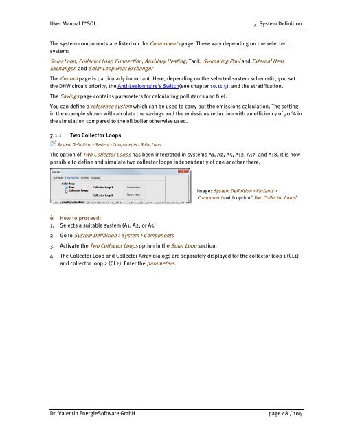
3. Activate the Two Collector Loops option in the Solar Loop section.<br />
Image: System Definition > Variants ><br />
Components with option "Two Collector loops"<br />
4. The Collector Loop and Collector Array dialogs are separately displayed for the collector loop 1 (CL1)<br />
and collector loop 2 (CL2). Enter the parameters.<br />
Dr. <strong>Valentin</strong> Energie<strong>Software</strong> GmbH page 48 / 104