Manual T*SOL basic 5.0 - Valentin Software
Manual T*SOL basic 5.0 - Valentin Software
Manual T*SOL basic 5.0 - Valentin Software

Create successful ePaper yourself
Turn your PDF publications into a flip-book with our unique Google optimized e-Paper software.
7 System Definition User <strong>Manual</strong> <strong>T*SOL</strong><br />
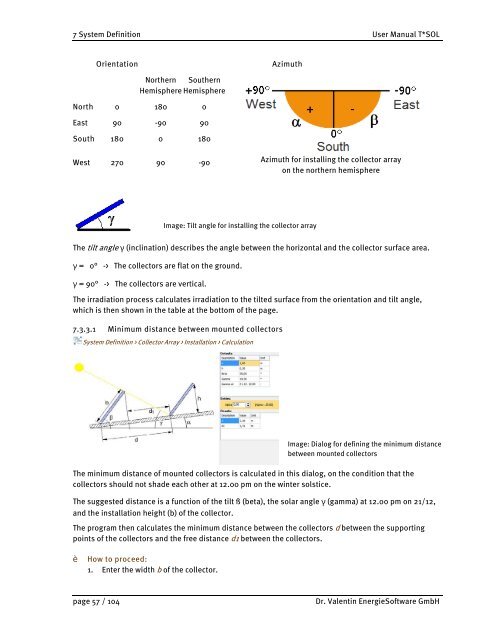
Orientation Azimuth<br />
Northern Southern<br />
Hemisphere Hemisphere<br />
North 0 180 0<br />
East 90 -90 90<br />
South 180 0 180<br />
West 270 90 -90<br />
Image: Tilt angle for installing the collector array<br />
Azimuth for installing the collector array<br />
on the northern hemisphere<br />
The tilt angle γ (inclination) describes the angle between the horizontal and the collector surface area.<br />
γ = 0° -> The collectors are flat on the ground.<br />
γ = 90° -> The collectors are vertical.<br />
The irradiation process calculates irradiation to the tilted surface from the orientation and tilt angle,<br />
which is then shown in the table at the bottom of the page.<br />
7.3.3.1 Minimum distance between mounted collectors<br />
System Definition > Collector Array > Installation > Calculation<br />
Image: Dialog for defining the minimum distance<br />
between mounted collectors<br />
The minimum distance of mounted collectors is calculated in this dialog, on the condition that the<br />
collectors should not shade each other at 12.00 pm on the winter solstice.<br />
The suggested distance is a function of the tilt ß (beta), the solar angle γ (gamma) at 12.00 pm on 21/12,<br />
and the installation height (b) of the collector.<br />
The program then calculates the minimum distance between the collectors d between the supporting<br />
points of the collectors and the free distance d1 between the collectors.<br />
Ł How to proceed:<br />
1. Enter the width b of the collector.<br />
page 57 / 104 Dr. <strong>Valentin</strong> Energie<strong>Software</strong> GmbH