Protein Expression and Purification Series - Bio-Rad
Protein Expression and Purification Series - Bio-Rad
Protein Expression and Purification Series - Bio-Rad

You also want an ePaper? Increase the reach of your titles
YUMPU automatically turns print PDFs into web optimized ePapers that Google loves.
<strong>Protein</strong> <strong>Expression</strong> <strong>and</strong> <strong>Purification</strong> <strong>Series</strong><br />
Final Check Before Starting Method<br />
1.<br />
2.<br />
3.<br />
4.<br />
Check for leaks or air in the lines.<br />
Check to make sure that your buffer inlet lines are at the bottom of the beakers containing Buffer A<br />
<strong>and</strong> Buffer B.<br />
Make sure that you have at least 50 ml of Buffer A <strong>and</strong> 20 ml of Buffer B.<br />
Place collection tubes in the fraction collector rack in the first two columns (30 tubes total) for the<br />
<strong>Bio</strong>Frac fraction collector or the first 30 spaces for the Model 2110 fraction collector.<br />
5. If you are using LP DataView software, press STOP on the software menu. Press CLEAR to clear<br />
all previous information. A menu box will appear. Choose “NO.” Press RECORD to record your<br />
purification run.<br />
Load Sample Loop with GST-DHFR-His Soluble Fraction<br />
1.<br />
2.<br />
3.<br />
4.<br />
5.<br />
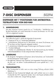
Make sure the MV-6 injector valve knob counter is turned<br />
counterclockwise (left) as far as it will go (Figure 7.10).<br />
Draw 5 ml of the soluble fraction of GST-DHFR-His into the 10 ml<br />
syringe. Avoid pulling in any air bubbles. If you have more than 5 ml of<br />
soluble fraction, you can draw the entire fraction into the syringe.<br />
Make sure to have the waste port tubing of the MV-6 injector valve<br />
over a waste beaker.<br />
Insert the syringe in the top port of the MV-6 injector valve <strong>and</strong> fill the<br />
sample loop. The excess water that was in the sample loop from the<br />
cleaning of the loop will be pushed out of the waste port.<br />
Note: Avoid pushing air bubbles into the sample loop since these will<br />
flow into the column <strong>and</strong> through the detectors.<br />
Leave the syringe in the port when you have injected the sample; this prevents the sample from<br />
siphoning out of the loop.<br />
Start Method<br />
1. Press the Run mode key.<br />
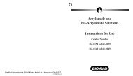
2. Immediately turn the injector valve knob clockwise<br />
(to the right) as far as it will go (Figure 7.11).<br />
Figure 7.11. MV-6 injection port in the INJECT position. The<br />
inject position (turned fully clockwise) opens up the fluid pathway<br />
so that the buffer coming from the pump will push the sample out<br />
of the sample loop <strong>and</strong> onto the column.<br />
Chapter 7: <strong>Purification</strong> Protocol for <strong>Bio</strong>Logic LP System<br />
149<br />
Figure 7.10. MV-6 in Sample<br />
Load position, turned as far left<br />
as possible.<br />
CHAPTER 7<br />
BIOLOGIC LP SYSTEM<br />
PROTOCOL