Protein Expression and Purification Series - Bio-Rad
Protein Expression and Purification Series - Bio-Rad
Protein Expression and Purification Series - Bio-Rad

Create successful ePaper yourself
Turn your PDF publications into a flip-book with our unique Google optimized e-Paper software.
CHAPTER 8<br />
BIOLOGIC DUOFLOW<br />
PROTOCOL<br />
<strong>Protein</strong> <strong>Expression</strong> <strong>and</strong> <strong>Purification</strong> <strong>Series</strong><br />
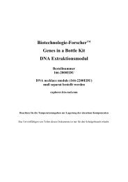
Figure 8.5. The purge buttons for Pump A <strong>and</strong> Pump B on the DuoFlow workstation. When the purge buttons on the<br />
workstation front are pushed, the workstation pumps will run at a default flow rate of 10 ml/min <strong>and</strong> the indicator light will flash<br />
green. Many columns cannot withst<strong>and</strong> the pressure that this would generate <strong>and</strong> therefore, it is critical that the AVR7-3 valve has<br />
been set to the P (Purge) setting to ensure that the fluid flow will exit to waste <strong>and</strong> not flow onto the column at this flow rate.<br />
1.4 Manual Control of the Workstation Pumps<br />
The workstation pump parameters are set from the Manual screen either by clicking in the appropriate field<br />
<strong>and</strong> entering a value from the keyboard or by using the arrows (Figure 8.6).<br />
1.<br />
2.<br />
3.<br />
4.<br />
5.<br />
6.<br />
7.<br />
Set the flow rate to 1.00 ml/min by typing 1.00 into the Flowrate box or using the up/down arrows.<br />
Set the Inlet A composition to 100%.<br />
Set the high pressure limit to 200 psi <strong>and</strong> the low pressure limit to 0 psi.<br />
To start the pump, click the Start button. The green light for Pump A should be lit.<br />
Allow Pump A to run for three minutes.<br />
With Pump A running, change the Inlet B value to 100% (notice that Inlet A automatically changes to<br />
0%) <strong>and</strong> press the Set button to initiate the change. The green light for Pump A should go off <strong>and</strong> the<br />
green light for Pump B should turn on.<br />
Allow Pump B to run for three minutes <strong>and</strong> then press Stop to stop the pump.<br />
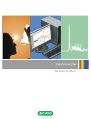
Figure 8.6. Manual pump control. The flow rate for an F10 pump head<br />
system can be set between 0.01 to 10 ml/min. The maximum flow rate<br />
is determined by the type of column that is being used. Some resins<br />
cannot withst<strong>and</strong> the pressure that builds from a high flowrate <strong>and</strong> will be<br />
crushed (such as soft agarose-based beads). Other resins can withst<strong>and</strong><br />
much higher pressures/flow rates without being damaged. The Inlet A<br />
<strong>and</strong> Inlet B settings determine how much buffer is pulled from each port.<br />
Typical chromatography nomenclature refers to the percentage of buffer<br />
B that is being used. So if a 95% Buffer A <strong>and</strong> 5% Buffer B mixture was<br />
required, this would be referred to as 5% Buffer B. The High <strong>and</strong> Low<br />
limits are pressure limits that can be set to have the instrument turn off if<br />
they are exceeded or drop below the given values, respectively. These are<br />
used to protect the column from overpressuring <strong>and</strong> to stop the run if the<br />
pressure drops to zero, which is usually indicative of running out of buffer<br />
or having a large air bubble in the tubing.<br />
170 Chapter 8: <strong>Purification</strong> Protocol for <strong>Bio</strong>Logic DuoFlow System