Handbook for Bridge Inspections - TSP2
Handbook for Bridge Inspections - TSP2
Handbook for Bridge Inspections - TSP2

Create successful ePaper yourself
Turn your PDF publications into a flip-book with our unique Google optimized e-Paper software.
Hangers<br />
/ ® ®<br />
23456189<br />
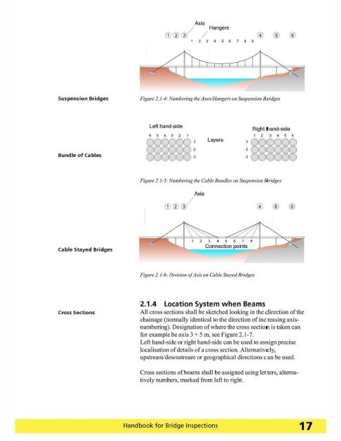
Suspension <strong>Bridge</strong>s<br />
Figllre 2. 1-4: .'Vllmbering 'he AxeslHangers on Suspension Br idges<br />
Bundle of Cables<br />
Left hand-side<br />
6 5 432<br />
~ :<br />
Layers<br />
:mm<br />
Right tland-side<br />
123456<br />
Figllre 2. 1-5: .'VlIIl1bering 'he Cable Bundles 011 S1Ispellsioll liridges<br />
@ ®<br />
®<br />
Cable Stayed <strong>Bridge</strong>s<br />
2345678<br />
Connection ints<br />
Figure 2./-6: Dirisioll of Axis 0 11 Cable Stayed <strong>Bridge</strong>s<br />
Cross Sections<br />
2.1.4 Location System when Beams<br />
All cross sections shall be sketched looking in the direction of the<br />
chainage (nonna1l y identical to the direction of inc reasing axisnumbering).<br />
Designation of where the cross sectioll is taken can<br />
<strong>for</strong> example be axis 3 + 5 m, see Figure 2. 1-7.<br />
Left hand-side or right hand-side can be used to assign precise<br />
localisation of details of a cross section. Alternative ly,<br />
upstream/downstream or geographical directions c an be used.<br />
Cross secti ons of beams shall be assigned using letters, alternati<br />
vely numbers, marked from left to right.<br />
<strong>Handbook</strong> <strong>for</strong> <strong>Bridge</strong> <strong>Inspections</strong> 17