Handbook for Bridge Inspections - TSP2
Handbook for Bridge Inspections - TSP2
Handbook for Bridge Inspections - TSP2

You also want an ePaper? Increase the reach of your titles
YUMPU automatically turns print PDFs into web optimized ePapers that Google loves.
grouting gun pushed all the way to the bottom of the hol e. As the<br />
hol e fill s up the tube is gradually removed.<br />
Holes resulting from Core Drilling or larger Chiselled Cuts<br />
Dust and loose particles should be cleaned out with water after<br />
which any water remaining should be dried up . The mortar to be<br />
used <strong>for</strong> the repair(s) should be mixed to the required consistency<br />
and put in the ho le(s) to 2·3cm below the surface level. Once the<br />
mortar has set the remainder of the hole should be fill ed with mar·<br />
tar flush with the surface. Immediately thereafter a layer of thick<br />
elastic cement-based coating should be applied to the surface.<br />
Mortar used to repair holes resulting from core dri ll ing or larger<br />
chiselled cuts should satisfy the same requirements <strong>for</strong> mortar<br />
used during mechanical repairs.<br />
Purpose<br />
Procedures<br />
7.3. 1 Locating the Rein<strong>for</strong>cement - Measuring<br />
its Cover<br />
To locate the rein<strong>for</strong>cement and measure its cover.<br />
Reference is made to the Nonvegian Public Roads Administrati on<br />
<strong>Handbook</strong> No. 015: "Tests carried out in the Field", Method<br />
No. 15.542.<br />
The description given in the procedural code of how cover is measured<br />
should be used to obtain accurate measurements. However,<br />
these can be simpl ified as follows if the measurements are more in<br />
the nature of a spot test:<br />
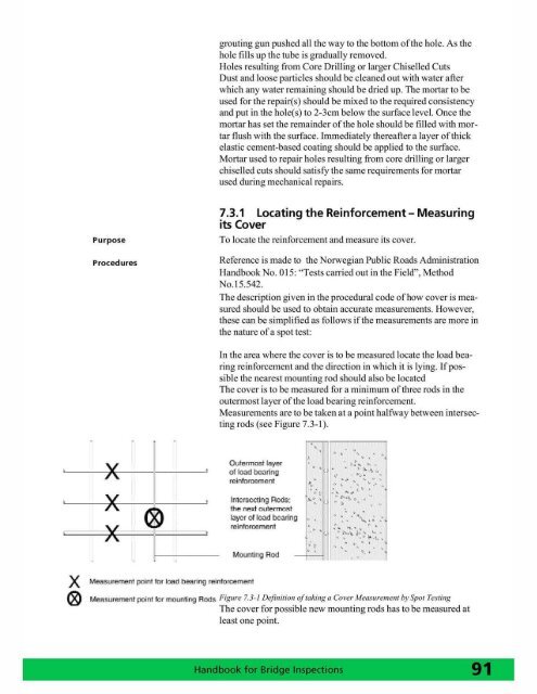
In the area where the cover is to be measured locate the load bearing<br />
rein<strong>for</strong>cement and the direction in which it is lyi ng. If possible<br />
the nearest mounting rod should also be located<br />
The cover is to be measured <strong>for</strong> a minimum of three rods in the<br />
outennost layer of the load bearing rein<strong>for</strong>cement.<br />
Measurements are to be taken at a point halfway between intersecting<br />
rods (see Figure 7.3- 1).<br />
x<br />
®<br />
x<br />
x<br />
o x<br />
,<br />
Me8wrernent poinllOl I~d l;JeR ri~ reinloroem ent<br />
Outermost layer<br />
of load bearing<br />
rein<strong>for</strong>(lement<br />
>,·-1 . Intersecting Rods: ,....,. ,<br />
• I<br />
Itw! nf!'xt outermo!ll<br />
layer of load bc.aIing ~.<br />
Mounting fl od<br />
,<br />
..,<br />
. . .<br />
" . ,~~ .<br />
, '<br />
,... ......<br />
......<br />
.,<br />
' ~,'\ ~ ....... ,<br />
. ,<br />
. . ,<br />
" •• II' .\, •<br />
",.<br />
MeR!2IurerTlPrnt point tm mountin9 Rnds Figure 7. 3-1 Defil1ition a/takil1g a Cover MC(Jsuremelll by Spot Testing<br />
The cover <strong>for</strong> possibl e new mounting rods has to be measured at<br />
least one point.