Optimod-AM 9400 V1.2 Operating Manual - Orban
Optimod-AM 9400 V1.2 Operating Manual - Orban
Optimod-AM 9400 V1.2 Operating Manual - Orban
- No tags were found...
You also want an ePaper? Increase the reach of your titles
YUMPU automatically turns print PDFs into web optimized ePapers that Google loves.
1-22<br />
INTRODUCTION ORBAN MODEL <strong>9400</strong><br />
to prevent overloading or overmodulation of the transmission system. This peak<br />
overload level is defined differently, system to system.<br />
In FM modulation, it is the maximum-permitted RF carrier frequency deviation. In<br />
<strong>AM</strong> modulation, it is negative carrier pinch-off. In analog telephone / post / PTT<br />
transmission, it is the level above which serious crosstalk into other channels occurs,<br />
or the level at which the amplifiers in the channel overload. In digital, it is the largest<br />
possible digital word.<br />
For metering, the transmission engineer uses an oscilloscope, absolute peak-sensing<br />
meter, calibrated peak-sensing LED indicator, or a modulation meter. A modulation<br />
meter usually has two components — a semi-peak reading meter (like a PPM), and a<br />
peak-indicating light, which is calibrated to turn on whenever the instantaneous<br />
peak modulation exceeds the overmodulation threshold.<br />
Line-Up Facilities<br />
Metering of Levels<br />
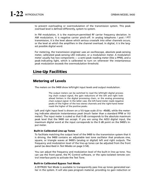
The meters on the <strong>9400</strong> show left/right input levels and output modulation.<br />
The output meters can be switched to read the left/right digital processing<br />
chain output signal, the gain reductions of the left and right lookahead<br />
limiters in the digital processing chain, or the analog processing<br />
chain output signal. In the latter case, the left-hand meter reads negative<br />
peaks of the higher of the two stereo channels and the right-hand meter<br />
reads the higher of the positive peaks.<br />
Left and right input level is shown on a VU-type scale 0 to –40dB), while the metering<br />
indicates absolute instantaneous peak (much faster than a standard PPM or VU<br />
meter). The input meter is scaled so that 0 dB corresponds to the absolute maximum<br />
peak level that the <strong>9400</strong> can accept. If you are using the AES3 digital input, the<br />
maximum digital word at the input corresponds to the 0 dB point on the <strong>9400</strong>’s input<br />
meter.<br />
Built-in Calibrated Line-up Tones<br />
To facilitate matching the output level of the <strong>9400</strong> to the transmission system that it<br />
is driving, the <strong>9400</strong> contains an adjustable test tone oscillator that produces sine,<br />
square, or triangle waves at <strong>9400</strong>’s (analog or digital) left and right outputs. The<br />
frequency and modulation level of the line-up tones can be adjusted from the front<br />
panel (as described in Test Modes on page 3-54).<br />
You can adjust the frequency and modulation level of the built-in line-up tone. You<br />
can use the front panel, the PC Control software, or the opto-isolated remote control<br />
interface ports to activate the Test Tone.<br />
Built-in Calibrated Bypass Test Mode<br />
A BYPASS Test Mode is available to transparently pass line-up tones generated earlier<br />
in the system. It will also pass program material, providing no gain reduction or


![[PDF] Using the ITU BS.1770-2 and CBS Loudness Meters ... - Orban](https://img.yumpu.com/50629372/1/190x245/pdf-using-the-itu-bs1770-2-and-cbs-loudness-meters-orban.jpg?quality=85)



![[PDF] Optimod-FM Feature Comparison - Orban](https://img.yumpu.com/41741615/1/190x245/pdf-optimod-fm-feature-comparison-orban.jpg?quality=85)
