Mr. Erik Milito - The House Committee on Natural Resources ...
Mr. Erik Milito - The House Committee on Natural Resources ...
Mr. Erik Milito - The House Committee on Natural Resources ...

Create successful ePaper yourself
Turn your PDF publications into a flip-book with our unique Google optimized e-Paper software.
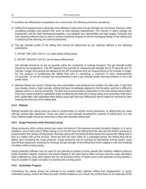
32 API STANDARD 65-2<br />
To c<strong>on</strong>diti<strong>on</strong> the drilling fluid in preparati<strong>on</strong> for a cement job, the following should be c<strong>on</strong>sidered.<br />
a) Drilling fluid displacement is generally more effective if yield point and gel strength are minimized. However, other<br />
competing priorities may prevent this, such as hole cleaning requirements. <str<strong>on</strong>g>The</str<strong>on</strong>g> manner in which cuttings are<br />
transported, and the ideal rheological properties, vary between low, intermediate and high angles. Hydraulic and<br />
hole cleaning software may be used to c<strong>on</strong>duct sensitivity analysis to aid the rheological design of the drilling fluid<br />
in balancing hole cleaning and cement placement.<br />
b) <str<strong>on</strong>g>The</str<strong>on</strong>g> gel strength profile of the drilling fluid should be determined as per methods defined in the following<br />
publicati<strong>on</strong>s:<br />
1) API RP 13B-1/ISO 10414-1, for water-based drilling fluids,<br />
2) API RP 13B-2/ISO 10414-2, for oil-based drilling fluids.<br />
Gel strength should be as low as possible within the c<strong>on</strong>straints of cuttings transport. <str<strong>on</strong>g>The</str<strong>on</strong>g> gel strength profile<br />
should be n<strong>on</strong>-progressive. <str<strong>on</strong>g>The</str<strong>on</strong>g> API standard time periods for measuring gel strength are at 10 sec<strong>on</strong>ds and 10<br />
minutes. L<strong>on</strong>ger time periods are allowed by the API procedures such as measurements at 30 minutes or l<strong>on</strong>ger.<br />
For the purpose of c<strong>on</strong>diti<strong>on</strong>ing the drilling fluid prior to cementing, a minimum of three measurements<br />
(10 sec<strong>on</strong>ds, 10 and 30 minutes) are recommended to plot a gel strength profile showing whether or not a flat<br />
profile exists.<br />
c) Maintain filtrate loss c<strong>on</strong>trol. Filtrate loss into a permeable z<strong>on</strong>e enhances the creati<strong>on</strong> of a filter cake. A high fluid<br />
loss creates a thick or high viscosity, drilling fluid layer immediately adjacent to the formati<strong>on</strong> wall that is difficult to<br />
displace prior to or during cementing. <str<strong>on</strong>g>The</str<strong>on</strong>g> fluid loss recommended is dependent <strong>on</strong> the hole secti<strong>on</strong> being drilled.<br />
Fluid loss c<strong>on</strong>trol should be maintained while c<strong>on</strong>diti<strong>on</strong>ing the hole and running casing and cementing. Note that a<br />
thick, gelled filter cake deposited while drilling using high fluid loss drilling fluid cannot easily be removed by later<br />
lowering the fluid loss of the drilling fluid.<br />
5.8.4 Rathole<br />
Rathole beneath the casing shoe can lead to c<strong>on</strong>taminati<strong>on</strong> of cement during placement, or drilling fluid can swap<br />
with the cement after placement. <str<strong>on</strong>g>The</str<strong>on</strong>g>se can result in poor strength development, pockets of drilling fluid, or a wet<br />
shoe. Rathole length should be minimized or filled with densified drilling fluid.<br />
5.8.5 Surge Pressures while Running Casing<br />
Surge pressures while running casing may cause lost returns if the pressure exceeds formati<strong>on</strong> integrity, or in some<br />
situati<strong>on</strong>s, loss of well c<strong>on</strong>trol. When casing is run into the hole, the drilling fluid flow rate (and the fricti<strong>on</strong> pressure) is<br />
proporti<strong>on</strong>al to the casing running speed. Running casing with c<strong>on</strong>venti<strong>on</strong>al float equipment causes the drilling fluid to<br />
flow at a higher rate up the annulus. Since the well has been static for a prol<strong>on</strong>ged period, the drilling fluid will be<br />
gelled, also increasing the surge pressure. Surge pressures can be reduced by decreasing running speed, using<br />
auto-fill float equipment, lowering the rheology and gel strength of the drilling fluid and/or staging in hole and breaking<br />
circulati<strong>on</strong> while running casing.<br />
Surge predicti<strong>on</strong> software may be used for job planning to predict running speeds that maintain wellbore pressure<br />
below formati<strong>on</strong> integrity. However, the lowest integrity in the open hole is often unknown and the surge calculati<strong>on</strong><br />
itself is affected by many other factors that are not precisely known. If losses occur at the planned running speeds, it<br />
may be possible to regain circulati<strong>on</strong> by lowering the running speed.<br />
5.8.6 Centralizer Program<br />
Centralizing the casing across the intervals to be isolated helps optimize drilling fluid displacement. In poorly<br />
centralized casing, cement will follow the path of least resistance; as a result, the cement flows <strong>on</strong> the wide side of the