Mr. Erik Milito - The House Committee on Natural Resources ...
Mr. Erik Milito - The House Committee on Natural Resources ...
Mr. Erik Milito - The House Committee on Natural Resources ...

Create successful ePaper yourself
Turn your PDF publications into a flip-book with our unique Google optimized e-Paper software.
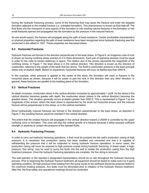
16 API GUIDANCE DOCUMENT HF1<br />
During the hydraulic fracturing process, some of the fracturing fluid may leave the fracture and enter the targeted<br />
formati<strong>on</strong> adjacent to the created fracture (i.e. untreated formati<strong>on</strong>). This phenomen<strong>on</strong> is known as fluid leak-off. <str<strong>on</strong>g>The</str<strong>on</strong>g><br />
fluid flows into the micropore or pore spaces of the formati<strong>on</strong> or into existing natural fractures in the formati<strong>on</strong> or into<br />
small fractures opened and propagated into the formati<strong>on</strong> by the pressure in the induced fracture.<br />
As <strong>on</strong>e would expect, the fracture will propagate al<strong>on</strong>g the path of least resistance. Certain predictable characteristics<br />
or physical properties regarding the path of least resistance have been recognized since hydraulic fracturing was first<br />
c<strong>on</strong>ducted in the oilfield in 1947. <str<strong>on</strong>g>The</str<strong>on</strong>g>se properties are discussed below.<br />
9.2 Horiz<strong>on</strong>tal Fractures<br />
Hydraulic fractures are formed in the directi<strong>on</strong> perpendicular to the least stress. In Figure 6, an imaginary cube of rock<br />
is shown as having c<strong>on</strong>fining stress exerted <strong>on</strong> it in three dimensi<strong>on</strong>s. Each pair of opposing stresses must be equal<br />
in order for the cube to remain stati<strong>on</strong>ary in space. <str<strong>on</strong>g>The</str<strong>on</strong>g> relative size of the arrows represents the magnitude of the<br />
c<strong>on</strong>fining stress. In Figure 7, the least stress is in the vertical directi<strong>on</strong>. This directi<strong>on</strong> is known as the directi<strong>on</strong> of<br />
overburden, referring to the weight of the earth that lies above. <str<strong>on</strong>g>The</str<strong>on</strong>g> Earth’s overburden pressure is the least principal<br />
stress <strong>on</strong>ly at shallow depth. Based <strong>on</strong> experience, horiz<strong>on</strong>tal fractures will occur at depths less than 2000 ft.<br />
In this example, when pressure is applied to the center of this block, the formati<strong>on</strong> will crack or fracture in the<br />
horiz<strong>on</strong>tal plane as shown, because it will be easier to part the rock in this directi<strong>on</strong> than any other directi<strong>on</strong>. In<br />
general, these fractures are parallel to the bedding plane of the formati<strong>on</strong>.<br />
9.3 Vertical Fractures<br />
As depth increases, overburden stress in the vertical directi<strong>on</strong> increases by approximately 1 psi/ft. As the stress in the<br />
vertical directi<strong>on</strong> becomes greater with depth, the overburden stress (stress in the vertical directi<strong>on</strong>) becomes the<br />
greatest stress. This situati<strong>on</strong> generally occurs at depths greater than 2000 ft. This is represented in Figure 7 by the<br />
magnitude of the arrows, where the least stress is represented by the small red horiz<strong>on</strong>tal arrows, and the induced<br />
fracture will be perpendicular to this stress, or in the vertical orientati<strong>on</strong>.<br />
Since hydraulically induced fractures are formed in the directi<strong>on</strong> perpendicular to the least stress, as depicted in<br />
Figure 7, the resulting fracture would be oriented in the vertical directi<strong>on</strong>.<br />
<str<strong>on</strong>g>The</str<strong>on</strong>g> extent that the created fracture will propagate in the vertical directi<strong>on</strong> toward a USDW is c<strong>on</strong>trolled by the upper<br />
c<strong>on</strong>fining z<strong>on</strong>e or formati<strong>on</strong>. This z<strong>on</strong>e will stop the vertical growth of a fracture because it either possess sufficient<br />
strength or elasticity to c<strong>on</strong>tain the pressure of the injected fluids.<br />
9.4 Hydraulic Fracturing Process<br />
In order to carry out hydraulic fracturing operati<strong>on</strong>s, a fluid must be pumped into the well’s producti<strong>on</strong> casing at high<br />
pressure. It is necessary that producti<strong>on</strong> casing has been installed and cemented and that it is capable of<br />
withstanding the pressure that it will be subjected to during hydraulic fracture operati<strong>on</strong>s. In some cases, the<br />
producti<strong>on</strong> casing will never be exposed to high pressure except during hydraulic fracturing. In these cases, a highpressure<br />
“frac string” may be used to pump the fluids into the well to isolate the producti<strong>on</strong> casing from the high<br />
treatment pressure. Once the hydraulic fracturing operati<strong>on</strong>s are complete, the frac string is removed.<br />
<str<strong>on</strong>g>The</str<strong>on</strong>g> well operator or the operator’s designated representative should be <strong>on</strong> site throughout the hydraulic fracturing<br />
process. Prior to beginning the hydraulic fracture treatment, all equipment should be tested to make sure it is in good<br />
operating c<strong>on</strong>diti<strong>on</strong>. All high-pressure lines leading from the pump trucks to the wellhead should be pressure tested to<br />
the maximum treating pressure. Any leaks must be eliminated prior to initiati<strong>on</strong> of the hydraulic fracture treatment.<br />
After this, the final safety and operati<strong>on</strong>al meetings should be c<strong>on</strong>ducted.