

view user manual (pdf) - dyna-flo control valves
view user manual (pdf) - dyna-flo control valves
view user manual (pdf) - dyna-flo control valves

Create successful ePaper yourself
Turn your PDF publications into a flip-book with our unique Google optimized e-Paper software.
Design and Functional Principle<br />
9<br />
3 6.1 2 1 12 7<br />
1<br />
138<br />
10<br />
--<br />
+<br />
238 9<br />
10<br />
5<br />
6.2<br />
4<br />
8<br />
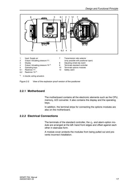
1 Input: Supply air 7 Transmission ratio selector<br />
2 Output: Actuating pressure Y1 (only possible with positioner open)<br />
3 Display 8 Adjusting wheel slip clutch<br />
4 Output: Actuating pressure Y2 *) 9 Terminals standard <strong>control</strong>ler<br />
5 Operating keys 10 Terminals options modules<br />
6.1 Restrictor Y1 12 Safety catch<br />
6.2 Restrictor Y2 *)<br />
*) in double--acting actuators<br />
Figure 2-2<br />
View of the explosion proof version of the positioner<br />
2.2.1 Motherboard<br />
2.2.2 Electrical Connections<br />
The motherboard contains all the electronic elements such as the CPU,<br />
memory, A/D converter. It also contains the display and the operating<br />
keys.<br />
In addition, the terminal strips for connecting the options modules are<br />
also on the motherboard.<br />
The terminals of the standard <strong>control</strong>ler, the J y - and alarm-option module<br />
are arranged at the left--hand front edges and offset against each<br />
other in staircase form.<br />
A module cover protects the modules from being pulled out and prevents<br />
incorrect installation.<br />
SIPART PS2 Manual<br />
A5E00074631-03<br />
17


