

view user manual (pdf) - dyna-flo control valves
view user manual (pdf) - dyna-flo control valves
view user manual (pdf) - dyna-flo control valves

You also want an ePaper? Increase the reach of your titles
YUMPU automatically turns print PDFs into web optimized ePapers that Google loves.
Design and Functional Principle<br />
2.2.4 Mounting Kit<br />
The positioner can be mounted on almost all actuators with the appropriate<br />
mounting kit.<br />
2.2.5 Purge air switching (not in the explosion proof version)<br />
The purge air switch is accessible above the pneumatic terminal strip<br />
with the housing open (figure 2-6). In the IN position the inside of the<br />
housing is purged with very small amounts of clean, dry instrument air.<br />
In the OUT position the purge air is fed directly to the outside air.<br />
Figure 2-6<br />
Purge air switch on the valve block, <strong>view</strong> of the positioner onto pneumatic connection side<br />
with cover open<br />
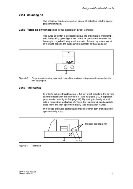
2.2.6 Restrictors<br />
In order to achieve travel times of > 1.5 s in small actuators, the air rate<br />
can be reduced with the restrictors Y1 and Y2 (figure 2-7, in explosion<br />
proof version, see figure 2-4, page 18). By turning to the right the air<br />
rate is reduced up to shutting off. To set the restrictors it is advisable to<br />
close them and then open them slowly (see initialization RUN3).<br />
In the case of double-acting <strong>valves</strong> make sure that both chokes are set<br />
approximately equal.<br />
Hexagon socket 2.5 mm<br />
Y1 Y2<br />
Figure 2-7<br />
Restrictors<br />
SIPART PS2 Manual<br />
A5E00074631-03<br />
21


