

SERVICE MANUAL - Alarko Carrier
SERVICE MANUAL - Alarko Carrier
SERVICE MANUAL - Alarko Carrier

Create successful ePaper yourself
Turn your PDF publications into a flip-book with our unique Google optimized e-Paper software.
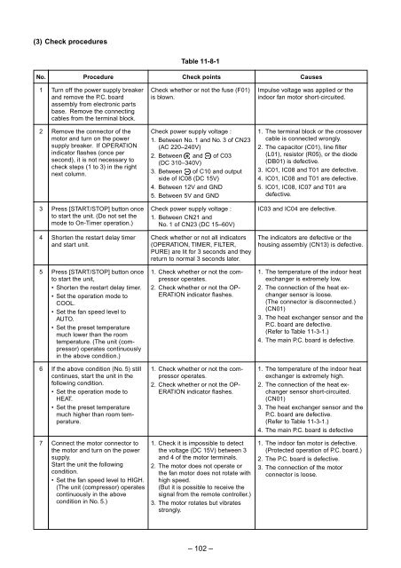
(3) Check procedures<br />
Table 11-8-1<br />
No.<br />
Procedure<br />
Check points<br />
Causes<br />
1<br />
Turn off the power supply breaker<br />
and remove the P.C. board<br />
assembly from electronic parts<br />
base. Remove the connecting<br />
cables from the terminal block.<br />
Check whether or not the fuse (F01)<br />
is blown.<br />
Impulse voltage was applied or the<br />
indoor fan motor short-circuited.<br />
2<br />
Remove the connector of the<br />
motor and turn on the power<br />
supply breaker. If OPERATION<br />
indicator flashes (once per<br />
second), it is not necessary to<br />
check steps (1 to 3) in the right<br />
next column.<br />
Check power supply voltage :<br />
1. Between No. 1 and No. 3 of CN23<br />
(AC 220–240V)<br />
2. Between and of C03<br />
(DC 310–340V)<br />
3. Between of C10 and output<br />
side of IC08 (DC 15V)<br />
4. Between 12V and GND<br />
5. Between 5V and GND<br />
1. The terminal block or the crossover<br />
cable is connected wrongly.<br />
2. The capacitor (C01), line filter<br />
(L01), resistor (R05), or the diode<br />
(DB01) is defective.<br />
3. IC01, IC08 and T01 are defective.<br />
4. IC01, IC08 and T01 are defective.<br />
5. IC01, IC08, IC07 and T01 are<br />
defective.<br />
3<br />
Press [START/STOP] button once<br />
to start the unit. (Do not set the<br />
mode to On-Timer operation.)<br />
Check power supply voltage :<br />
1. Between CN21 and<br />
No. 1 of CN23 (DC 15–60V)<br />
IC03 and IC04 are defective.<br />
4<br />
Shorten the restart delay timer<br />
and start unit.<br />
Check whether or not all indicators<br />
(OPERATION, TIMER, FILTER,<br />
PURE) are lit for 3 seconds and they<br />
return to normal 3 seconds later.<br />
The indicators are defective or the<br />
housing assembly (CN13) is defective.<br />
5<br />
Press [START/STOP] button once<br />
to start the unit,<br />
• Shorten the restart delay timer.<br />
• Set the operation mode to<br />
COOL.<br />
• Set the fan speed level to<br />
AUTO.<br />
• Set the preset temperature<br />
much lower than the room<br />
temperature. (The unit (compressor)<br />
operates continuously<br />
in the above condition.)<br />
1. Check whether or not the compressor<br />
operates.<br />
2. Check whether or not the OP-<br />
ERATION indicator flashes.<br />
1. The temperature of the indoor heat<br />
exchanger is extremely low.<br />
2. The connection of the heat exchanger<br />
sensor is loose.<br />
(The connector is disconnected.)<br />
(CN01)<br />
3. The heat exchanger sensor and the<br />
P.C. board are defective.<br />
(Refer to Table 11-3-1.)<br />
4. The main P.C. board is defective.<br />
6<br />
If the above condition (No. 5) still<br />
continues, start the unit in the<br />
following condition.<br />
• Set the operation mode to<br />
HEAT.<br />
• Set the preset temperature<br />
much higher than room temperature.<br />
1. Check whether or not the compressor<br />
operates.<br />
2. Check whether or not the OP-<br />
ERATION indicator flashes.<br />
1. The temperature of the indoor heat<br />
exchanger is extremely high.<br />
2. The connection of the heat exchanger<br />
sensor short-circuited.<br />
(CN01)<br />
3. The heat exchanger sensor and the<br />
P.C. board are defective.<br />
(Refer to Table 11-3-1.)<br />
4. The main P.C. board is defective<br />
7<br />
Connect the motor connector to<br />
the motor and turn on the power<br />
supply.<br />
Start the unit the following<br />
condition.<br />
• Set the fan speed level to HIGH.<br />
(The unit (compressor) operates<br />
continuously in the above<br />
condition in No. 5.)<br />
1. Check it is impossible to detect<br />
the voltage (DC 15V) between 3<br />
and 4 of the motor terminals.<br />
2. The motor does not operate or<br />
the fan motor does not rotate with<br />
high speed.<br />
(But it is possible to receive the<br />
signal from the remote controller.)<br />
3. The motor rotates but vibrates<br />
strongly.<br />
1. The indoor fan motor is defective.<br />
(Protected operation of P.C. board.)<br />
2. The P.C. board is defective.<br />
3. The connection of the motor<br />
connector is loose.<br />
– 102 –


