

SERVICE MANUAL - Alarko Carrier
SERVICE MANUAL - Alarko Carrier
SERVICE MANUAL - Alarko Carrier

You also want an ePaper? Increase the reach of your titles
YUMPU automatically turns print PDFs into web optimized ePapers that Google loves.
Useful Functions<br />
Self-Diagnosis by LED Indication<br />
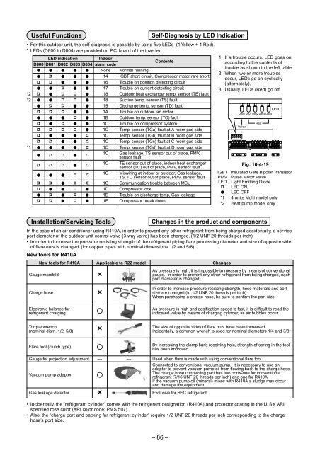
• For this outdoor unit, the self-diagnosis is possible by using five LEDs (1 Yellow + 4 Red).<br />
* LEDs (D800 to D804) are provided on P.C. board of the inverter.<br />
*2<br />
*2<br />
*1<br />
LED indication<br />
D800 D801 D802 D803 D804<br />
l l l l l<br />
l ¤ l l l<br />
¤ ¤ l l l<br />
l l ¤ l l<br />
¤ l ¤ ¤ l<br />
l l ¤ ¤ l<br />
l ¤ ¤ l l<br />
¤ ¤ ¤ l l<br />
l l l ¤ l<br />
¤ l ¤ l l<br />
¤ ¤ ¤ ¤ l<br />
¤ l l l ¤<br />
¤ ¤ l l ¤<br />
l l l l ¤<br />
l ¤ ¤ l ¤<br />
¤ ¤ ¤ l ¤<br />
l l l ¤ ¤<br />
¤ ¤ l ¤ ¤<br />
¤ l l ¤ l<br />
l ¤ l ¤ l<br />
¤ ¤ l ¤ l<br />
Indoor<br />
alarm code<br />
None<br />
14<br />
16<br />
17<br />
18<br />
18<br />
19<br />
1A<br />
1B<br />
1C<br />
1C<br />
1C<br />
1C<br />
1C<br />
1C<br />
1C<br />
1C<br />
1C<br />
1D<br />
1E<br />
1F<br />
Contents<br />
Normal running<br />
IGBT short circuit, Compressor motor rare short<br />
Trouble on position detecting circuit<br />
Trouble on current detecting circuit<br />
Outdoor heat exchanger temp. sensor (TE) fault<br />
Suction temp. sensor (TS) fault<br />
Discharge temp. sensor (TD) fault<br />
Trouble on outdoor fan motor<br />
Outdoor temp. sensor (TO) fault<br />
Trouble on compressor system<br />
Temp. sensor (TGa) fault at A room gas side<br />
Temp. sensor (TGb) fault at B room gas side<br />
Temp. sensor (TGc) fault at C room gas side<br />
Temp. sensor (TGd) fault at D room gas side<br />
Gas leakage, TS sensor out of place, PMV,<br />
sensor fault<br />
TE sensor out of place, indoor heat exchanger<br />
sensor (TC) out of place, PMV, sensor fault<br />
Miswiring at indoor or outdoor, Gas leakage,<br />
TS, TC sensor out of place, PMV, sensor fault<br />
Communication trouble between MCU<br />
Compressor lock<br />
Trouble on discharge temp, Gas leakage<br />
Compressor break down<br />
1. If a trouble occurs, LED goes on<br />
according to the contents of<br />
trouble as shown in the left table.<br />
2. When two or more troubles<br />
occur, LEDs go on cyclically<br />
(alternately).<br />
3. Usually, LEDs (Red) go off.<br />
LED<br />
D800 D801 D802 D803 D804<br />
Yellow<br />
Red<br />
Fig. 10-4-19<br />
IGBT : Insulated Gate Bipolar Transistor<br />
PMV : Pulse Motor Valve<br />
LED : Light Emitting Diode<br />
¤ : LED ON<br />
l : LED OFF<br />
*1 : 4 units Multi model only<br />
*2 : Heat pump model only<br />
Installation/Servicing Tools<br />
Changes in the product and components<br />
In the case of an air conditioner using R410A, in order to prevent any other refrigerant from being charged accidentally, a service<br />
port diameter of the outdoor unit control valve (3 way valve) has been changed. (1/2 UNF 20 threads per inch)<br />
• In order to increase the pressure resisting strength of the refrigerant piping flare processing diameter and size of opposite side<br />
of flare nuts is changed. (for copper pipes with nominal dimensions 1/2 and 5/8)<br />
New tools for R410A<br />
New tools for R410A<br />
Gauge manifold<br />
Charge hose<br />
Applicable to R22 model<br />
×<br />
×<br />
Changes<br />
As pressure is high, it is impossible to measure by means of conventional<br />
gauge. In order to prevent any other refrigerant from being charged, each<br />
port diameter is changed.<br />
In order to increase pressure resisting strength, hose materials and port<br />
size are changed (to 1/2 UNF 20 threads per inch).<br />
When purchasing a charge hose, be sure to confirm the port size.<br />
Electronic balance for<br />
refrigerant charging<br />
Torque wrench<br />
(nominal diam. 1/2, 5/8)<br />
Flare tool (clutch type)<br />
¡<br />
×<br />
¡<br />
As pressure is high and gasification speed is fast, it is difficult to read the<br />
indicated value by means of charging cylinder, as air bubbles occur.<br />
The size of opposite sides of flare nuts have been increased.<br />
Incidentally, a common wrench is used for nominal diameters 1/4 and 3/8.<br />
By increasing the clamp bar’s receiving hole, strength of spring in the tool<br />
has been improved.<br />
Gauge for projection adjustment<br />
Vacuum pump adapter<br />
Gas leakage detector<br />
— —<br />
¡<br />
×<br />
Used when flare is made with using conventional flare tool.<br />
Connected to conventional vacuum pump. It is necessary to use an<br />
adapter to prevent vacuum pump oil from flowing back to the charge hose.<br />
The charge hose connecting part has two ports-one for conventional<br />
refrigerant (7/16 UNF 20 threads per inch) and one for R410A.<br />
If the vacuum pump oil (mineral) mixes with R410A a sludge may occur<br />
and damage the equipment.<br />
Exclusive for HFC refrigerant.<br />
• Incidentally, the “refrigerant cylinder” comes with the refrigerant designation (R410A) and protector coating in the U. S’s ARI<br />
specified rose color (ARI color code: PMS 507).<br />
• Also, the “charge port and packing for refrigerant cylinder” require 1/2 UNF 20 threads per inch corresponding to the charge<br />
hose’s port size.<br />
– 86 –


