

SERVICE MANUAL - Alarko Carrier
SERVICE MANUAL - Alarko Carrier
SERVICE MANUAL - Alarko Carrier

You also want an ePaper? Increase the reach of your titles
YUMPU automatically turns print PDFs into web optimized ePapers that Google loves.
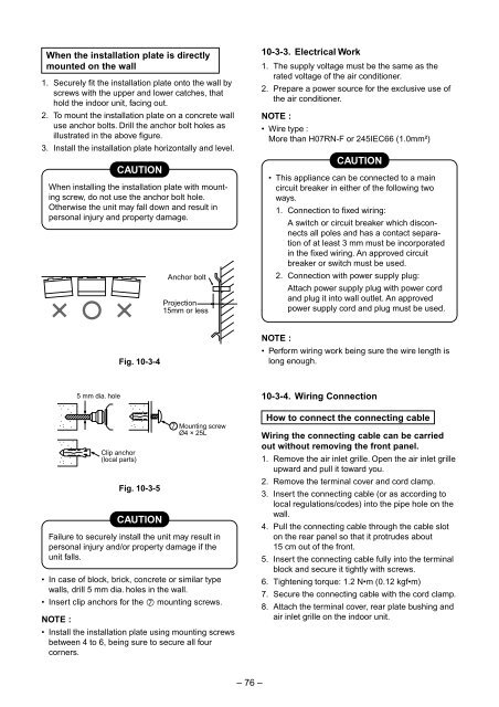
When the installation plate is directly<br />
mounted on the wall<br />
1. Securely fit the installation plate onto the wall by<br />
screws with the upper and lower catches, that<br />
hold the indoor unit, facing out.<br />
2. To mount the installation plate on a concrete wall<br />
use anchor bolts. Drill the anchor bolt holes as<br />
illustrated in the above figure.<br />
3. Install the installation plate horizontally and level.<br />
CAUTION<br />
When installing the installation plate with mounting<br />
screw, do not use the anchor bolt hole.<br />
Otherwise the unit may fall down and result in<br />
personal injury and property damage.<br />
Anchor bolt<br />
Projection<br />
15mm or less<br />
10-3-3. Electrical Work<br />
1. The supply voltage must be the same as the<br />
rated voltage of the air conditioner.<br />
2. Prepare a power source for the exclusive use of<br />
the air conditioner.<br />
NOTE :<br />
• Wire type :<br />
More than H07RN-F or 245IEC66 (1.0mm²)<br />
CAUTION<br />
• This appliance can be connected to a main<br />
circuit breaker in either of the following two<br />
ways.<br />
1. Connection to fixed wiring:<br />
A switch or circuit breaker which disconnects<br />
all poles and has a contact separation<br />
of at least 3 mm must be incorporated<br />
in the fixed wiring. An approved circuit<br />
breaker or switch must be used.<br />
2. Connection with power supply plug:<br />
Attach power supply plug with power cord<br />
and plug it into wall outlet. An approved<br />
power supply cord and plug must be used.<br />
Fig. 10-3-4<br />
NOTE :<br />
• Perform wiring work being sure the wire length is<br />
long enough.<br />
Fig. 10-3-5<br />
CAUTION<br />
Failure to securely install the unit may result in<br />
personal injury and/or property damage if the<br />
unit falls.<br />
• In case of block, brick, concrete or similar type<br />
walls, drill 5 mm dia. holes in the wall.<br />
• Insert clip anchors for the ‡ mounting screws.<br />
NOTE :<br />
5 mm dia. hole<br />
Clip anchor<br />
(local parts)<br />
7 Mounting screw<br />
Ø4 × 25L<br />
• Install the installation plate using mounting screws<br />
between 4 to 6, being sure to secure all four<br />
corners.<br />
10-3-4. Wiring Connection<br />
How to connect the connecting cable<br />
Wiring the connecting cable can be carried<br />
out without removing the front panel.<br />
1. Remove the air inlet grille. Open the air inlet grille<br />
upward and pull it toward you.<br />
2. Remove the terminal cover and cord clamp.<br />
3. Insert the connecting cable (or as according to<br />
local regulations/codes) into the pipe hole on the<br />
wall.<br />
4. Pull the connecting cable through the cable slot<br />
on the rear panel so that it protrudes about<br />
15 cm out of the front.<br />
5. Insert the connecting cable fully into the terminal<br />
block and secure it tightly with screws.<br />
6. Tightening torque: 1.2 N•m (0.12 kgf•m)<br />
7. Secure the connecting cable with the cord clamp.<br />
8. Attach the terminal cover, rear plate bushing and<br />
air inlet grille on the indoor unit.<br />
– 76 –


