

SERVICE MANUAL - Alarko Carrier
SERVICE MANUAL - Alarko Carrier
SERVICE MANUAL - Alarko Carrier

Create successful ePaper yourself
Turn your PDF publications into a flip-book with our unique Google optimized e-Paper software.
Item<br />
Operation flow and applicable data, etc.<br />
Description<br />
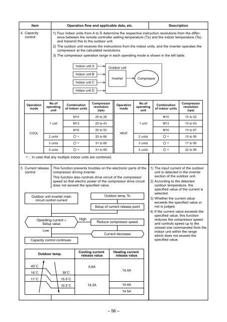
4. Capacity<br />
control<br />
1) Four indoor units from A to D determine the respective instruction revolutions from the difference<br />
between the remote controller setting temperature (Ts) and the indoor temperature (Ta),<br />
and transmit this to the outdoor unit.<br />
2) The outdoor unit receives the instructions from the indoor units, and the inverter operates the<br />
compressor at the calculated revolutions.<br />
3) The compressor operation range in each operating mode is shown in the left table.<br />
Indoor unit A<br />
Indoor unit B<br />
Indoor unit C<br />
Indoor unit D<br />
Outdoor unit<br />
Inverter<br />
Compressor<br />
Operation<br />
mode<br />
No.of<br />
operating<br />
unit<br />
Combination<br />
of indoor units<br />
Compressor<br />
revolution<br />
(rps)<br />
Operation<br />
mode<br />
No.of<br />
operating<br />
unit<br />
Combination<br />
of indoor units<br />
Compressor<br />
revolution<br />
(rps)<br />
M10<br />
20 to 28<br />
M10<br />
15 to 52<br />
1 unit<br />
M13<br />
20 to 43<br />
1 unit<br />
M13<br />
15 to 63<br />
COOL<br />
2 units<br />
M16<br />
¡ ∗<br />
20 to 53<br />
20 to 66<br />
HEAT<br />
2 units<br />
M16<br />
¡ ∗<br />
15 to 67<br />
15 to 90<br />
3 units<br />
¡ ∗<br />
31 to 69<br />
3 units<br />
¡ ∗<br />
17 to 90<br />
4 units<br />
¡ ∗<br />
31 to 69<br />
4 units<br />
¡ ∗<br />
22 to 90<br />
∗ : In case that any multiple indoor units are combined.<br />
5. Current release<br />
control<br />
Outdoor unit inverter main<br />
circuit control current<br />
Operating current £<br />
Setup value<br />
Low<br />
Capacity control continues.<br />
This function prevents troubles on the electronic parts of the<br />
compressor driving inverter.<br />
This function also controls drive circuit of the compressor<br />
speed so that electric power of the compressor drive circuit<br />
does not exceed the specified value.<br />
High<br />
Outdoor temp. To<br />
Setup of current release point<br />
Reduce compressor speed<br />
Current decrease<br />
1) The input current of the outdoor<br />
unit is detected in the inverter<br />
section of the outdoor unit.<br />
2) According to the detected<br />
outdoor temperature, the<br />
specified value of the current is<br />
selected.<br />
3) Whether the current value<br />
exceeds the specified value or<br />
not is judged.<br />
4) If the current value exceeds the<br />
specified value, this function<br />
reduces the compressor speed<br />
and controls speed up to the<br />
closest one commanded from the<br />
indoor unit within the range<br />
which does not exceed the<br />
specified value.<br />
Outdoor temp.<br />
Cooling current<br />
release value<br />
Heating current<br />
release value<br />
40˚C 9.6A<br />
16˚C<br />
39˚C<br />
14.4A<br />
11˚C<br />
15.5˚C<br />
10.5˚C<br />
14.2A<br />
14.4A<br />
14.5A<br />
– 56 –


