SERVICE MANUAL - Alarko Carrier
SERVICE MANUAL - Alarko Carrier
SERVICE MANUAL - Alarko Carrier
Create successful ePaper yourself
Turn your PDF publications into a flip-book with our unique Google optimized e-Paper software.
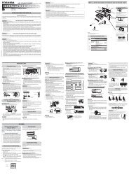
10. INSTALLATION PROCEDURE<br />
10-1. Safety Cautions<br />
Hook<br />
47 mm or more<br />
1 Installation plate<br />
Hook<br />
For the rear left and left piping<br />
Wall<br />
140 mm or more<br />
Hook<br />
74 mm<br />
or more<br />
Insert the cushion between<br />
the indoor unit and wall, and<br />
tilt the indoor unit for better<br />
installation work.<br />
7 Mounting screw<br />
Do not allow the drain hose<br />
to become slack.<br />
5 Zeolite-plus filter<br />
6 Plasma pure filter<br />
Z Shield pipe<br />
(for extension<br />
drain hose)<br />
Cut the piping<br />
hole slightly<br />
sloped<br />
Make sure the drain hose is<br />
sloped downward.<br />
Air filters<br />
Y<br />
The auxiliary piping can be<br />
connected at the left, rear left,<br />
rear right, right, bottom right or<br />
bottom left as shown below.<br />
2 Wireless<br />
remote controller<br />
100 mm or more<br />
from wall<br />
4 Remote controller holder<br />
(Mounting holes on both<br />
left and right sides)<br />
(C)<br />
80 mm or more only<br />
when unobstructed to<br />
the front and both sides<br />
In principle,<br />
leave open<br />
50 mm or more<br />
from wall<br />
(D)<br />
Right<br />
Rear<br />
right<br />
Bottom left<br />
Left<br />
Bottom right Rear left<br />
8 Remote controller<br />
holder mounting screw<br />
200 mm<br />
or more<br />
(B)<br />
When installing the outdoor unit,<br />
leave open in at least two of<br />
directions (A), (B), (C) and (D)<br />
shown in the right figure.<br />
Ensure sufficient space<br />
to allow drainage<br />
(A)<br />
250 mm or more<br />
from wall<br />
Power cord<br />
Extension drain hose<br />
(Option: RB-821SW)<br />
As shown in the figure, position power cord and<br />
connecting cable downward, and lead out along<br />
piping connection port.<br />
Insulate the refrigerant pipes<br />
separately, not together.<br />
6 mm thick heat resisting<br />
polyethylene foam<br />
Before installing the wireless remote controller<br />
• With the remote controller cover<br />
removed, correctly load the<br />
supplied batteries while<br />
observing their polarity.<br />
Cover<br />
3 Batteries<br />
2 Wireless remote controller<br />
– 72 –


