

SERVICE MANUAL - Alarko Carrier
SERVICE MANUAL - Alarko Carrier
SERVICE MANUAL - Alarko Carrier

Create successful ePaper yourself
Turn your PDF publications into a flip-book with our unique Google optimized e-Paper software.
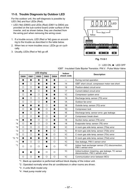
11-5. Trouble Diagnosis by Outdoor LED<br />
For the outdoor unit, the self-diagnosis is possible by<br />
LED (Yel) and four LEDs (Red).<br />
• LED (Yel) (D800) and LEDs (Red) (D801 to D804) are<br />
provided on the sub-control board under surface of the<br />
inverter, and as shown below, they are checked from<br />
the wiring port when removing the wiring cover.<br />
LED<br />
D800 D801 D802 D803 D804<br />
Yellow<br />
Red<br />
1. If a trouble occurs, LED (Red or Yel) goes on according<br />
to the trouble as described in the table below.<br />
2. When two or more troubles occur, LEDs go on cyclically.<br />
3. Usually, LEDs (Red or Yel) go off.<br />
Fig. 11-5-1<br />
¡ : LED ON, l : LED OFF<br />
IGBT : Insulated Gate Bipolar Transistor, P.M.V. : Pulse Motor Valve<br />
LED display<br />
D800 D801 D802 D803 D804<br />
Indoor<br />
check code<br />
Description<br />
*4<br />
*4<br />
*2<br />
l l l l l<br />
l ¡ l l l<br />
¡ ¡ l l l<br />
l l ¡ l l<br />
¡ l ¡ l l<br />
l ¡ ¡ l l<br />
¡ ¡ ¡ l l<br />
l l l ¡ l<br />
¡ l l ¡ l<br />
l ¡ l ¡ l<br />
¡ ¡ l ¡ l<br />
l l ¡ ¡ l<br />
¡ l ¡ ¡ l<br />
¡ ¡ ¡ ¡ l<br />
—<br />
14<br />
16<br />
17<br />
1C<br />
19<br />
1A<br />
1B<br />
1D<br />
1E<br />
1F<br />
18<br />
18<br />
1C<br />
During normal operation<br />
IGBT short circuit, compressor motor rare short<br />
Position-detect circuit error<br />
Current-detect circuit error<br />
Compressor system error<br />
Discharge temp. sensor (TD) error<br />
Outdoor fan error<br />
Outside temp. sensor (TO) error<br />
Compressor lock<br />
Discharge temp. sensor error, gas leakage<br />
Compressor break down<br />
Suction temp. sensor (TS) error<br />
Evaporator temp. sensor (TE) error<br />
A room gas side temp. sensor (TGa) error<br />
*2<br />
¡ l l l ¡<br />
1C<br />
B room gas side temp. sensor (TGb) error<br />
*2<br />
¡ ¡ l l ¡<br />
1C<br />
C room gas side temp. sensor (TGc) error<br />
*2, *3<br />
*1<br />
l l l l ¡<br />
l ¡ ¡ l ¡<br />
1C<br />
1C<br />
D room gas side temp. sensor (TGd) error<br />
Gas leakage, P.M.V. sensor error<br />
*1<br />
¡ ¡ ¡ l ¡<br />
1C<br />
Indoor heat exchanger sensor (TC) disconnection,<br />
P.M.V. sensor error<br />
l l l ¡ ¡<br />
1C<br />
Indoor/outdoor miswiring, gas leakage, TC sensor<br />
disconnection, P.M.V. sensor error<br />
¡ ¡ l ¡ ¡<br />
1C<br />
Communication error between MCU<br />
*1 : Back-up operation is performed without block display of the indoor unit.<br />
*2 : Operated normally when the air conditioners in other rooms are driven.<br />
*3 : 4 units Multi model only<br />
*4 : Heat pump model only<br />
– 97 –


