

SERVICE MANUAL - Alarko Carrier
SERVICE MANUAL - Alarko Carrier
SERVICE MANUAL - Alarko Carrier

You also want an ePaper? Increase the reach of your titles
YUMPU automatically turns print PDFs into web optimized ePapers that Google loves.
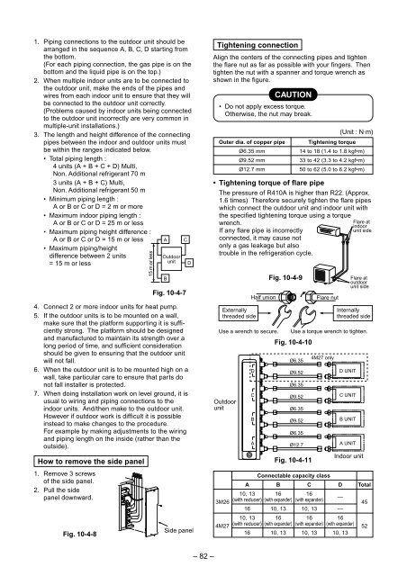
1. Piping connections to the outdoor unit should be<br />
arranged in the sequence A, B, C, D starting from<br />
the bottom.<br />
(For each piping connection, the gas pipe is on the<br />
bottom and the liquid pipe is on the top.)<br />
2. When multiple indoor units are to be connected to<br />
the outdoor unit, make the ends of the pipes and<br />
wires from each indoor unit to ensure that they will<br />
be connected to the outdoor unit correctly.<br />
(Problems caused by indoor units being connected<br />
to the outdoor unit incorrectly are very common in<br />
multiple-unit installations.)<br />
3. The length and height difference of the connecting<br />
pipes between the indoor and outdoor units must<br />
be within the ranges indicated below.<br />
• Total piping length :<br />
4 units (A + B + C + D) Multi,<br />
Non. Additional refrigerant 70 m<br />
3 units (A + B + C) Multi,<br />
Non. Additional refrigerant 50 m<br />
• Minimum piping length :<br />
A or B or C or D = 2 m or more<br />
• Maximum indoor piping length :<br />
A or B or C or D = 25 m or less<br />
• Maximum piping height difference :<br />
A or B or C or D = 15 m or less<br />
• Maximum piping/height<br />
difference between 2 units<br />
= 15 m or less<br />
Fig. 10-4-7<br />
4. Connect 2 or more indoor units for heat pump.<br />
5. If the outdoor units is to be mounted on a wall,<br />
make sure that the platform supporting it is sufficiently<br />
strong. The platform should be designed<br />
and manufactured to maintain its strength over a<br />
long period of time, and sufficient consideration<br />
should be given to ensuring that the outdoor unit<br />
will not fall.<br />
6. When the outdoor unit is to be mounted high on a<br />
wall, take particular care to ensure that parts do<br />
not fall installer is protected.<br />
7. When doing installation work on level ground, it is<br />
usual to wiring and piping connections to the<br />
indoor units. And/then make to the outdoor unit.<br />
However if outdoor work is difficult it is possible<br />
instead to make changes to the procedure.<br />
For example by making adjustments to the wiring<br />
and piping length on the inside (rather than the<br />
outside).<br />
How to remove the side panel<br />
1. Remove 3 screws<br />
of the side panel.<br />
2. Pull the side<br />
panel downward.<br />
Fig. 10-4-8<br />
15 m or less<br />
A<br />
Outdoor<br />
unit<br />
B<br />
C<br />
D<br />
Side panel<br />
Tightening connection<br />
Align the centers of the connecting pipes and tighten<br />
the flare nut as far as possible with your fingers. Then<br />
tighten the nut with a spanner and torque wrench as<br />
shown in the figure.<br />
CAUTION<br />
• Do not apply excess torque.<br />
Otherwise, the nut may break.<br />
Outer dia. of copper pipe<br />
• Tightening torque of flare pipe<br />
(Unit : N·m)<br />
The pressure of R410A is higher than R22. (Approx.<br />
1.6 times) Therefore securely tighten the flare pipes<br />
which connect the outdoor unit and indoor unit with<br />
the specified tightening torque using a torque<br />
wrench.<br />
If any flare pipe is incorrectly<br />
connected, it may cause not<br />
only a gas leakage but also<br />
trouble in the refrigeration cycle.<br />
3M26<br />
4M27<br />
Ø6.35 mm<br />
Ø9.52 mm<br />
Ø12.7 mm<br />
Externally<br />
threaded side<br />
Half union<br />
Use a wrench to secure.<br />
Outdoor<br />
unit<br />
D<br />
C<br />
B<br />
A<br />
Fig. 10-4-9<br />
Fig. 10-4-10<br />
Fig. 10-4-11<br />
Connectable capacity class<br />
A B C D Total<br />
10, 13 16 16<br />
(with reducer) (with expander) (with expander)<br />
Tightening torque<br />
14 to 18 (1.4 to 1.8 kgf•m)<br />
33 to 42 (3.3 to 4.2 kgf•m)<br />
50 to 62 (5.0 to 6.2 kgf•m)<br />
Flare nut<br />
—<br />
16 10, 13 10, 13 —<br />
10, 13 16 16 16<br />
(with reducer) (with expander) (with expander) (with expander)<br />
16 10, 13 10, 13 10, 13<br />
Internally<br />
threaded side<br />
Use a torque wrench to tighten.<br />
Ø6.35<br />
Ø9.52<br />
Ø6.35<br />
Ø9.52<br />
Ø6.35<br />
Ø9.52<br />
Ø6.35<br />
Ø12.7<br />
4M27 only<br />
D UNIT<br />
C UNIT<br />
B UNIT<br />
A UNIT<br />
Flare at<br />
indoor<br />
unit side<br />
Flare at<br />
outdoor<br />
unit side<br />
Indoor unit<br />
45<br />
52<br />
– 82 –


