

SERVICE MANUAL - Alarko Carrier
SERVICE MANUAL - Alarko Carrier
SERVICE MANUAL - Alarko Carrier

You also want an ePaper? Increase the reach of your titles
YUMPU automatically turns print PDFs into web optimized ePapers that Google loves.
No.<br />
Part name<br />
Procedures<br />
Remarks<br />
3<br />
Electric parts<br />
box assembly<br />
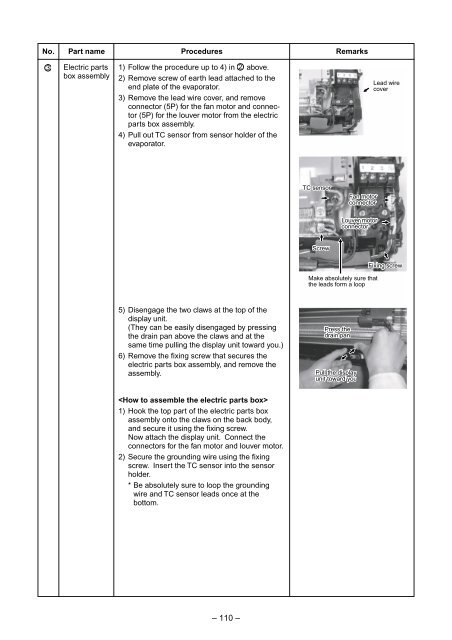
1) Follow the procedure up to 4) in 2 above.<br />
2) Remove screw of earth lead attached to the<br />
end plate of the evaporator.<br />
3) Remove the lead wire cover, and remove<br />
connector (5P) for the fan motor and connector<br />
(5P) for the louver motor from the electric<br />
parts box assembly.<br />
4) Pull out TC sensor from sensor holder of the<br />
evaporator.<br />
Lead wire<br />
cover<br />
TC sensor<br />
Fan motor<br />
connector<br />
Louver motor<br />
connector<br />
Screw<br />
Make absolutely sure that<br />
the leads form a loop<br />
Fixing screw<br />
5) Disengage the two claws at the top of the<br />
display unit.<br />
(They can be easily disengaged by pressing<br />
the drain pan above the claws and at the<br />
same time pulling the display unit toward you.)<br />
6) Remove the fixing screw that secures the<br />
electric parts box assembly, and remove the<br />
assembly.<br />
Press the<br />
drain pan<br />
Pull the display<br />
unit toward you<br />
<br />
1) Hook the top part of the electric parts box<br />
assembly onto the claws on the back body,<br />
and secure it using the fixing screw.<br />
Now attach the display unit. Connect the<br />
connectors for the fan motor and louver motor.<br />
2) Secure the grounding wire using the fixing<br />
screw. Insert the TC sensor into the sensor<br />
holder.<br />
* Be absolutely sure to loop the grounding<br />
wire and TC sensor leads once at the<br />
bottom.<br />
– 110 –


