

SERVICE MANUAL - Alarko Carrier
SERVICE MANUAL - Alarko Carrier
SERVICE MANUAL - Alarko Carrier

You also want an ePaper? Increase the reach of your titles
YUMPU automatically turns print PDFs into web optimized ePapers that Google loves.
10-4-10. Miswiring (Mispiping) Check<br />
Make sure that the wiring and piping for each room<br />
have the same alphabetical codes (A, B, C, D).<br />
Connect and secure the power cord.<br />
Use the power cord/cables with thickness, type and<br />
protective devices specified in this manual.<br />
Insulate the unused cords (conductors) with PVC<br />
tape.<br />
1. Turn on the power breaker.<br />
2. Open side panel of the outdoor unit.<br />
3. Set the all indoor units to COOL mode.<br />
• It is unnecessary to set the temperature.<br />
• Miswiring check can not be executed when<br />
outdoor air temperature is 5°C or less.<br />
4. Start the check.<br />
• Disconnect the miswiring check connector<br />
(color : Red) from P.C. board of inverter.<br />
5. During check (Check time 3 to 20 minutes).<br />
• When an error describes in the table below<br />
occurred check operation stops and error code<br />
is displayed on LED.<br />
6. After check, the result of check is displayed on<br />
LED.<br />
• The Comp. stop when miswiring (mispiping)<br />
error occurred.<br />
• Confirm the contents of table below.<br />
• Turn off the power breaker.<br />
• Correct miswiring/mispiping.<br />
• Execute the check operation again.<br />
• Automatically return to the normal operation<br />
when it is normal.<br />
7. Return to normal operation.<br />
• To return to the normal operation during check<br />
operation or after miswiring (mispiping) error is<br />
determined, connect the miswiring check<br />
connector.<br />
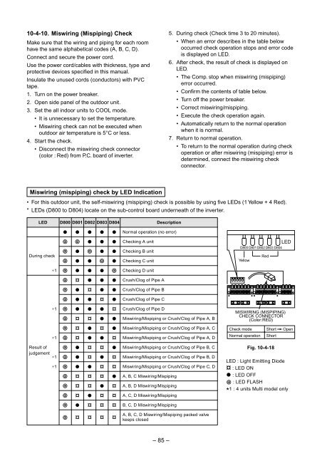
Miswiring (mispiping) check by LED Indication<br />
• For this outdoor unit, the self-miswiring (mispiping) check is possible by using five LEDs (1 Yellow + 4 Red).<br />
* LEDs (D800 to D804) locate on the sub-control board underneath of the inverter.<br />
LED<br />
During check<br />
∗1<br />
∗1<br />
∗1<br />
Result of<br />
judgement<br />
∗1<br />
∗1<br />
D800 D801 D802 D803 D804<br />
l l l l l<br />
¥ ¥ l l l<br />
¥ l ¥ l l<br />
¥ l l ¥ l<br />
¥ l l l ¥<br />
¥ ¤ l l l<br />
¥ l ¤ l l<br />
¥ l l ¤ l<br />
¥ l l l ¤<br />
¥ ¤ ¤ l l<br />
¥ ¤ l ¤ l<br />
¥ ¤ l l ¤<br />
¥ l ¤ ¤ l<br />
¥ l ¤ l ¤<br />
¥ l l ¤ ¤<br />
¥ ¤ ¤ ¤ l<br />
¥ ¤ ¤ l ¤<br />
¥ ¤ l ¤ ¤<br />
¥ l ¤ ¤ ¤<br />
¥ ¤ ¤ ¤ ¤<br />
Description<br />
Normal operation (no error)<br />
Checking A unit<br />
Checking B unit<br />
Checking C unit<br />
Checking D unit<br />
Crush/Clog of Pipe A<br />
Crush/Clog of Pipe B<br />
Crush/Clog of Pipe C<br />
Crush/Clog of Pipe D<br />
Miswiring/Mispiping or Crush/Clog of Pipe A, B<br />
Miswiring/Mispiping or Crush/Clog of Pipe A, C<br />
Miswiring/Mispiping or Crush/Clog of Pipe A, D<br />
Miswiring/Mispiping or Crush/Clog of Pipe B, C<br />
Miswiring/Mispiping or Crush/Clog of Pipe B, D<br />
Miswiring/Mispiping or Crush/Clog of Pipe C, D<br />
A, B, C Miswiring/Mispiping<br />
A, B, D Miswiring/Mispiping<br />
A, C, D Miswiring/Mispiping<br />
B, C, D Miswiring/Mispiping<br />
A, B, C, D Miswiring/Mispiping packed valve<br />
keeps closed<br />
LED<br />
D800 D801 D802 D803 D804<br />
Red<br />
Yellow<br />
MISWIRING (MISPIPING)<br />
CHECK CONNECTOR<br />
(Color:RED)<br />
Check mode<br />
Normal operation<br />
Short<br />
Short<br />
Fig. 10-4-18<br />
Open<br />
LED : Light Emitting Diode<br />
¤ : LED ON<br />
l : LED OFF<br />
¥ : LED FLASH<br />
1 : 4 units Multi model only<br />
*<br />
– 85 –


