

SERVICE MANUAL - Alarko Carrier
SERVICE MANUAL - Alarko Carrier
SERVICE MANUAL - Alarko Carrier

You also want an ePaper? Increase the reach of your titles
YUMPU automatically turns print PDFs into web optimized ePapers that Google loves.
11-3-2. Caution at Servicing<br />
1. After servicing, press the START/STOP button to return to the normal mode.<br />
2. After servicing by the check code, turn off breaker of the power supply, and turn on breaker of the power<br />
supply again so that memory in the microcomputer returns the initial status.<br />
However, the check codes are not deleted even if the power supply is turned off because they are stored in<br />
the fixed memory.<br />
3. After servicing, press [CLR] button under check mode status and then send the check code “7F” to the<br />
indoor unit. The error code stored in memory is cleared.<br />
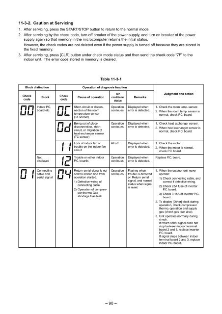
Table 11-3-1<br />
Block distinction<br />
Operation of diagnosis function<br />
Check<br />
code<br />
Block<br />
Check<br />
code<br />
Cause of operation<br />
Air<br />
conditioner<br />
status<br />
Remarks<br />
Judgment and action<br />
Indoor P.C.<br />
board etc.<br />
Short-circuit or disconnection<br />
of the room<br />
temperature sensor<br />
(TA sensor).<br />
Operation<br />
continues.<br />
Displayed when<br />
error is detected.<br />
1. Check the room temp. sensor.<br />
2. When the room temp. sensor is<br />
normal, check P.C. board.<br />
Being out of place,<br />
disconnection, shortcircuit,<br />
or migration of<br />
heat exchanger sensor<br />
(TC sensor)<br />
Operation<br />
continues.<br />
Displayed when<br />
error is detected.<br />
1. Check heat exchanger sensor.<br />
2. When heat exchanger sensor is<br />
normal, check P.C. board.<br />
Lock of indoor fan or<br />
trouble on the indoor fan<br />
circuit<br />
All off<br />
Displayed when<br />
error is detected.<br />
1. Check the motor.<br />
2. When the motor is normal,<br />
check P.C. board.<br />
Not<br />
displayed<br />
Trouble on other indoor<br />
P.C. boards<br />
Operation<br />
continues.<br />
Displayed when<br />
error is detected.<br />
Replace P.C. board.<br />
Connecting<br />
cable and<br />
serial signal<br />
Return serial signal is not<br />
sent to indoor side from<br />
operation started.<br />
1) Defective wiring of<br />
connecting cable<br />
2) Operation of compressor<br />
thermo Gas<br />
shortage Gas leak<br />
Operation<br />
continues.<br />
Flashes when<br />
trouble is detected<br />
on Return serial<br />
signal, and normal<br />
status when signal<br />
is reset.<br />
1. When the outdoor unit never<br />
operate:<br />
1) Check connecting cable, and<br />
correct if defective wiring.<br />
2) Check 25A fuse of inverter<br />
P.C. board.<br />
3) Check 3.15A of inverter P.C.<br />
board.<br />
2. To display [Other] block during<br />
operation, check compressor<br />
thermo. operation and supply<br />
gas (check gas leak also).<br />
3. Unit operates normally during<br />
check.<br />
If return serial signal does not<br />
stop between indoor terminal<br />
board 2 and 3, replace inverter<br />
P.C. board.<br />
If signal stops between indoor<br />
terminal board 2 and 3, replace<br />
indoor P.C. board.<br />
– 90 –


