

Modifications for the ICOM - RogerK
Modifications for the ICOM - RogerK
Modifications for the ICOM - RogerK
- No tags were found...

You also want an ePaper? Increase the reach of your titles
YUMPU automatically turns print PDFs into web optimized ePapers that Google loves.
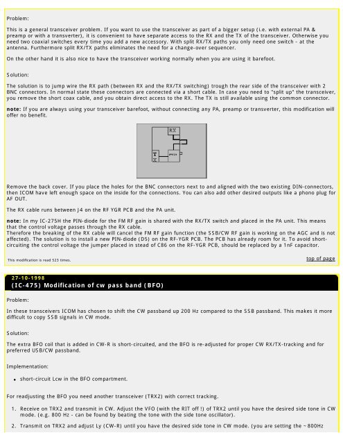
Problem:This is a general transceiver problem. If you want to use <strong>the</strong> transceiver as part of a bigger setup (i.e. with external PA &preamp or with a transverter), it is convenient to have separate access to <strong>the</strong> RX and <strong>the</strong> TX of <strong>the</strong> transceiver. O<strong>the</strong>rwise youneed two coaxial switches every time you add a new accessory. With split RX/TX paths you only need one switch - at <strong>the</strong>antenna. Fur<strong>the</strong>rmore split RX/TX paths eliminates <strong>the</strong> need <strong>for</strong> a change-over sequencer.On <strong>the</strong> o<strong>the</strong>r hand it is also nice to have <strong>the</strong> transceiver working normally when you are using it barefoot.Solution:The solution is to jump wire <strong>the</strong> RX path (between RX and <strong>the</strong> RX/TX switching) trough <strong>the</strong> rear side of <strong>the</strong> transceiver with 2BNC connectors. In normal state <strong>the</strong>se connectors are connected via a short cable. In case you need to "split up" <strong>the</strong> transceiver,you remove <strong>the</strong> short coax cable, and you obtain direct access to <strong>the</strong> RX. The TX is still available using <strong>the</strong> common connector.note: If you are always using your transceiver barefoot, without connecting any PA, preamp or transverter, this modification willoffer no benefit.Remove <strong>the</strong> back cover. If you place <strong>the</strong> holes <strong>for</strong> <strong>the</strong> BNC connectors next to and aligned with <strong>the</strong> two existing DIN-connectors,<strong>the</strong>n <strong>ICOM</strong> have left enough space on <strong>the</strong> inside <strong>for</strong> <strong>the</strong> connections. You can also add o<strong>the</strong>r desired outputs like a phono plug <strong>for</strong>AF OUT.The RX cable runs between J4 on <strong>the</strong> RF YGR PCB and <strong>the</strong> PA unit.note: In my IC-275H <strong>the</strong> PIN-diode <strong>for</strong> <strong>the</strong> FM RF gain is shared with <strong>the</strong> RX/TX switch and placed in <strong>the</strong> PA unit. This meansthat <strong>the</strong> control voltage passes through <strong>the</strong> RX cable.There<strong>for</strong>e <strong>the</strong> breaking of <strong>the</strong> RX cable will cancel <strong>the</strong> FM RF gain function (<strong>the</strong> SSB/CW RF gain is working on <strong>the</strong> AGC and is notaffected). The solution is to install a new PIN-diode (D5) on <strong>the</strong> RF-YGR PCB. The PCB has already room <strong>for</strong> it. To avoid shortcircuiting<strong>the</strong> control voltage <strong>the</strong> jumper placed in stead of C86 on <strong>the</strong> RF-YGR PCB, should be replaced by a 1nF capacitor.This modification is read 523 times.top of page27-10-1998(IC-475) Modification of cw pass band (BFO)Problem:In <strong>the</strong>se transceivers <strong>ICOM</strong> has chosen to shift <strong>the</strong> CW passband up 200 Hz compared to <strong>the</strong> SSB passband. This makes it moredifficult to copy SSB signals in CW mode.Solution:The extra BFO coil that is added in CW-R is short-circuited, and <strong>the</strong> BFO is re-adjusted <strong>for</strong> proper CW RX/TX-tracking and <strong>for</strong>preferred USB/CW passband.Implementation:●short-circuit Lcw in <strong>the</strong> BFO compartment.For readjusting <strong>the</strong> BFO you need ano<strong>the</strong>r transceiver (TRX2) with correct tracking.1. Receive on TRX2 and transmit in CW. Adjust <strong>the</strong> VFO (with <strong>the</strong> RIT off !) of TRX2 until you have <strong>the</strong> desired side tone in CWmode. (e.g. 800 Hz - can be found by beating <strong>the</strong> tone with <strong>the</strong> side tone oscillator).2. Transmit on TRX2 and adjust Ly (CW-R) until you have <strong>the</strong> desired side tone in CW mode. (you are setting <strong>the</strong> ~800Hz


