

Modifications for the ICOM - RogerK
Modifications for the ICOM - RogerK
Modifications for the ICOM - RogerK
- No tags were found...

Create successful ePaper yourself
Turn your PDF publications into a flip-book with our unique Google optimized e-Paper software.
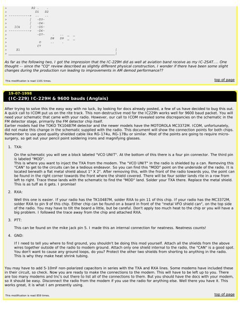
R2 . .> D1 D2> -----------+ .. ..> | -D3-> | -D4-> IC4 | -D5-> -----------+ -D6-> -D7- . .. _ _> D8 D9 _ _> O .. .> C7> X1 |> ________________________________________________________|As far as <strong>the</strong> following two, I got <strong>the</strong> impression that <strong>the</strong> IC-229H did as well at aviation band receive as my IC-2SAT.... Onethought -- since <strong>the</strong> "CQ" review described as slightly different physical construction, I wonder if <strong>the</strong>re have been some slightchanges during <strong>the</strong> production run leading to improvements in AM demod per<strong>for</strong>mance??This modification is read 1101 times.top of page19-07-1998(IC-229) IC-229H & 9600 bauds (Anglais)After trying to solve this <strong>the</strong> easy way with no luck, by looking <strong>for</strong> docs already posted, a few of us have decided to bug this out.A quick call to <strong>ICOM</strong> put us on <strong>the</strong> rite track. This non-destructive mod <strong>for</strong> <strong>the</strong> IC229h works well <strong>for</strong> 9600 baud packet. You willneed your schematic that came with your radio. However, our call to <strong>ICOM</strong> revealed some discrepancies on <strong>the</strong> schematic in <strong>the</strong>FM detector stage, primarily <strong>the</strong> FM detector chip itself.Earlier models had <strong>the</strong> TOKO TK10487M detector and <strong>the</strong> newer models have <strong>the</strong> MOTOROLA MC3372M. <strong>ICOM</strong>, un<strong>for</strong>tunately,did not make this change in <strong>the</strong> schematic supplied with <strong>the</strong> radio. This document will show <strong>the</strong> connection points <strong>for</strong> both chips.Remember to use good quality shielded cable like RG-174u, RG-178u or similar. Most of <strong>the</strong> points are going to require microsurgery,so get out your pencil point soldering irons and magnifying glasses.1. TXA:On <strong>the</strong> schematic you will see a block labeled "VCO UNIT". At <strong>the</strong> bottom of this <strong>the</strong>re is a four pin connector. The third pinis labeled "MOD".This is where you want to inject <strong>the</strong> TXA from <strong>the</strong> modem. The "VCO UNIT" in <strong>the</strong> radio is shielded by a can. Removing this"CAN" to get to <strong>the</strong> circuits can be a tedious endeavor. So you can find this "MOD" point on <strong>the</strong> underside of <strong>the</strong> radio. It islocated beneath a flat metal shield about 1" X 2". After removing this, with <strong>the</strong> front of <strong>the</strong> radio towards you, <strong>the</strong> point canbe found in <strong>the</strong> right corner towards <strong>the</strong> front where <strong>the</strong> shield covered. There will be four solder lands rite in a row fromleft to right. Trace <strong>the</strong>se lands with <strong>the</strong> schematic to find <strong>the</strong> "MOD" land. Solder your TXA <strong>the</strong>re. Replace <strong>the</strong> metal shield.This is as tuff as it gets. I promise!2. RXA:Well this one is easier. If your radio has <strong>the</strong> TK10487M, solder RXA to pin 11 of this chip. If your radio has <strong>the</strong> MC3372M,solder RXA to pin 9 of this chip. Ei<strong>the</strong>r chip can be found on a board in front of <strong>the</strong> "metal VFO shield can", on <strong>the</strong> top sideof <strong>the</strong> radio. You may have to tilt <strong>the</strong> board a little, but be careful. Don't apply too much heat to <strong>the</strong> chip or you will have abig problem. I followed <strong>the</strong> trace away from <strong>the</strong> chip and attached RXA.3. PTT:This can be found on <strong>the</strong> mike jack pin 5. I made this an internal connection <strong>for</strong> neatness. Neatness counts!4. GND:If I need to tell you where to find ground, you shouldn't be doing this mod yourself. Attach all <strong>the</strong> shields from <strong>the</strong> abovewires toge<strong>the</strong>r outside of <strong>the</strong> radio to modem ground. Attach only one shield internal to <strong>the</strong> radio, <strong>the</strong> "CAN" is a good spot.You don't want to cause any ground loops, do you? Protect <strong>the</strong> o<strong>the</strong>r two shields from shorting to anything in <strong>the</strong> radio.This is why <strong>the</strong>y make heat shrink tubing.You may have to add 5-10mF non-polarized capacitors in series with <strong>the</strong> TXA and RXA lines. Some modems have included <strong>the</strong>sein <strong>the</strong>ir circuit, so check. Now you are ready to make <strong>the</strong> connections to <strong>the</strong> modem. This will have to be left up to you. Thereare too many modems and tnc's out <strong>the</strong>re to list all of <strong>the</strong> connections to <strong>the</strong>m. But you should have <strong>the</strong> docs with your modem,so it should be easy. Disconnect <strong>the</strong> radio from <strong>the</strong> modem if you use <strong>the</strong> radio <strong>for</strong> anything else. Well <strong>the</strong>re you have it. Thisworks great, it is what I am presently using.This modification is read 859 times.top of page


